![]()
![]()
![]()
![]()
![]()
![]()
![]()
![]()
![]()
![]()
![]()
![]()
![]()
![]()
![]()
![]()

"It is
impossible for ideas to compete in the marketplace if no forum for
their presentation is provided or available." � �Thomas Mann, 1896
A Security Blueprint for Enterprise Networks
Authors: Sean Convery and Bernie Trudel are the
original authors of this White Paper
The second version was authored by Greg Abelar and Jason Halpern of the SAFE
Architecture Team.
Contributed by Cisco Systems, Inc.
Introduction
The SAFE Blueprint from Cisco Systems� is a secure blueprint for enterprise networks. Its principle goal is to provide best practices information on designing and implementing secure networks. SAFE takes a defense-in-depth approach to network security design, serving as a guide to network designers considering the security requirements of their networks. This type of design focuses on expected threats and their methods of mitigation, resulting in a layered approach to security where the failure of one security system is not likely to lead to the compromise of the rest of the network. Although this white paper is a product-agnostic document, the SAFE proof-of-concept lab is based on products from Cisco and its partners.
This document begins with an overview of the blueprint’s architecture, and then details the specific modules that make up the actual network design. When discussing each module, the first three sections describe the traffic flows, primary devices, and expected threats, with basic mitigation diagrams. Detailed technical analysis of the design follows, along with more detailed threat mitigation techniques and migration strategies.
Appendix A details the validation lab for SAFE and includes configuration snapshots.
Appendix B is a primer on network security. Readers unfamiliar with basic network security concepts are encouraged to read Appendix B before the rest of the document.
Appendix C contains definitions of the technical terms used in this document, and a legend for the included figures.
This document focuses on threats encountered in enterprise environments. Network designers who understand these threats can better decide where and how to deploy mitigation technologies. Without this understanding, deployments tend to be incorrectly configured, too focused on security devices, or lacking in threat response options. By taking the threat mitigation approach, this document provides network designers with information for making sound network security choices.
In addition to this enterprise document, Cisco has published several companion papers that address security issues for specific technologies and smaller-scaled networks (small, midsized, and remote).
These detailed documents can be found at the SAFE library at: www.cisco.com/go/safe and include:
-
SAFE: Extending the Security Blueprint to Small, Midsize, and Remote-User Networks
-
SAFE: IPSec Virtual Private Networks in Depth
-
SAFE: Wireless LAN Security in Depth — Version 2
-
SAFE: IP Telephony Security in Depth
-
SAFE: IDS Deployment, Tuning, and Logging in Depth
In addition, the SAFE library contains documents that provide a step-by-step analysis for combating specific high-profile network attacks. These are also located at www.cisco.com/go/safe and include:
-
SAFE: Worm Mitigation
-
SAFE: Layer 2 Best Practices
Audience
Though this document is technical in nature, it can be read at different levels of detail, depending on the reader. A network manager, for example, can read the introductory sections in each area to obtain an overview of network security design strategies and considerations. A network engineer or designer can read this document in its entirety and gain design information and threat analysis details, which are supported by configuration snapshots for the devices involved.
Caveats
This document presumes that you already have a security policy in place. Cisco does not recommend deploying security technologies without an associated policy. For further information about security policies and their use, consult the SANS Security Policy Project at: http://www.cisco.com/go/safe
This document directly addresses the needs of large enterprise customers. Readers interested in security best practices for smaller networks should read “SAFE: Extending the Security Blueprint to Small, Midsize, and Remote-User Networks” mentioned above.
Following the guidelines in this document does not guarantee a secure environment, or that you will prevent all intrusions. However, you can achieve reasonable security by establishing a good security policy, following the guidelines in this document, staying up to date on the latest developments in the hacker and security communities, and maintaining and monitoring all systems with sound system administration practices. This includes awareness of application security issue that are not comprehensively addressed in this paper.
Although VPNs are part of this architecture, they are not described in great detail in this document. Scaling details, resilience strategies, and other topics related to VPNs are covered in more detail in “SAFE VPN: IPSec Virtual Private Networks in Depth.” Like VPNs, identity strategies (including certificate authorities) are not discussed at any level of detail in this paper.
Wireless and IP telephony are also part of this architecture, but are not described in great detail in this document. More information is available in the “SAFE: Wireless LAN Security in Depth — Version 2” and “SAFE: IP Telephony Security in Depth” papers.
The SAFE blueprint uses products from Cisco and its partners. In this document, however, components are referred to by functional purpose rather than model number or name. During the validation of SAFE, real products were configured in the exact network implementations described in this document. Specific configuration snapshots from the lab are included in Appendix A.
Architecture Overview
Design Fundamentals
SAFE emulates as closely as possible the functional requirements of today’s enterprise networks. Implementation decisions varied depending on the network capabilities required. However, the following design objectives, listed in order of priority, guided the decision-making process.
-
Security and attack mitigation based on policy
-
Security implementation throughout the infrastructure (not just on specialized security devices)
-
Secure management and reporting
-
Authentication and authorization of devices, users, and administrators to critical network resources
-
Intrusion detection and prevention for critical resources and subnets
-
Support for emerging networked applications
First and foremost, SAFE is a security architecture. It must prevent most attacks from successfully affecting valuable network resources. The attacks that succeed in penetrating the first line of defense, or that originate from inside the network, must be accurately detected and quickly contained to minimize their effect on the rest of the network.
However, in being secure, the network must continue to provide critical services that users expect. Proper network security and good network functioning can be provided at the same time — the SAFE architecture is not a revolutionary way of designing networks, but merely a blueprint for making networks secure.
SAFE is also resilient and scalable. Resilience in networks includes physical redundancy to protect against device failure, whether from misconfiguration, physical failure, or network attack. Although simpler designs are possible, particularly if a network’s performance needs are not great, this document uses a complex design as an example because designing security in a complex environment is more involved than in simpler environments. Options to limit the complexity of the design are discussed throughout this document as well as in the other SAFE documents listed earlier. At many points in the network design process, an enterprise will need to choose between a network device with integrated functions and a specialized functional appliance. Integrated functioning is attractive because you can implement it on exiting equipment, the features can interoperate with the rest of the device to provide a better functional solution, or the features can be deployed incrementally to facilitate increased bandwidth requirements.
Appliances are often used when the depth of capability required is advanced or when performance needs require using specialized hardware (see Appendix D for information regarding integrated security blades for Layer 3 switches versus appliances). Decisions should be based on the capacity and capability of the appliance, not the integration advantage of the device. For example, sometimes you can choose an integrated higher-capacity router operating Cisco IOS� Software with the firewall feature, as opposed to a smaller Cisco IOS Software-based router with a separate firewall device. Throughout this architecture, both types of systems are used. Historically, most critical security functions have migrated toward dedicated appliances because of the performance requirements of large enterprise networks. Recently, however, integrated equipment has become much more attractive because of performance and capability enhancements. A security specialist now has more viable options when choosing between security appliances and integrated devices. If flexibility for expansion is a high priority, then line cards that plug into Layer 3 switches, routers, or PN concentrators may be attractive options.
Because a security architecture is an end-to-end concern, this paper will
address security issues ranging from the
network perimeter to the host application, and all elements in between.
SAFEv2 Updates
This document contains updates to the original SAFE document, published in the summer of 2000. Changes reflect new technologies in the security market between summer of 2000 and September 2003. These changes include the way enterprises are using the network to do business, and the way that hackers have chosen to exploit networks.
Enterprises are now extending the perimeter of the network, allowing partner connectivity, telecommuting, and application service provider (ASP) connectivity. Hackers are using more sophisticated techniques to sniff passwords, exploit Layer 2 switches, exploit routing protocols, and propagate worms that install malicious code on hosts. These and many more issues have implications that need to be addressed by modern security techniques. The technology and best practices added to this document to address these changes include:
-
Layer 2 attack mitigation schemes
-
Router hardening
-
Integrated security modules that plug into Layer 3 switches, including firewall, network intrusion detection system (IDS), Secure Sockets Layer (SSL) termination, and VPN termination
-
IDS deployment best practices
-
Design and best practices for a three-tier data center
-
Design and best practices for building a secure lab within an enterprise
-
Best practices for using host intrusion prevention software (HIPS) in the enterprise
-
Content-aware devices that can filter for viruses, proxy Web connections, and authenticate users
-
802.1x best practices
-
Recommendations for Simple Network Management Protocol Version 3 (SNMPv3), Secure Shell (SSH) Protocol, and SSL (encrypted management methods)
Module Concept
Although most enterprise networks have evolved with growing IT requirements, the SAFE architecture uses a modular approach, which has two main advantages. First, it allows the architecture to address the security relationship between the various functional blocks of the network. Second, it permits designers to evaluate and implement s curity on a module-by-module basis, instead of attempting the complete architecture i.e. a single phase.
Figure 1 illustrates the first layer of modularity in SAFE. Each block represents a functional area. The Internet service provider (ISP) module is not implemented by the enterprise, but is included to the extent that specific security features should be requested of an ISP in order to mitigate against certain attacks.
The second layer of modularity represents a view of the modules within each functional area (Figure 2). These modules perform specific roles in the network and have specific security requirements, but their sizes are not meant to reflect their scale in a real network. For example, the building module, which represents the end-user devices, may include 80 percent of the network devices. The security design of each module is described separately, but is validated as part of the complete enterprise design.
While most existing enterprise networks cannot be easily dissected into clear-cut modules, this approach provides a guide for implementing different security functions throughout the network. The authors do not expect network engineers to design networks identical to the SAFE implementation, but rather to use a combination of the modules described and integrate them into the existing network.
SAFE Axioms
This section outlines general best practices that apply to the entire SAFE blueprint. They are addressed here to avoid duplication throughout the individual modules.
Routers Are Targets
Router security is a critical element in any security deployment. Routers control access from every network to every network. They advertise networks and filter who can use them, and are potentially an attacker’s best friend. They should be secured to reduce the likelihood that they can be directly compromised. When securing routers, the primary areas of focus are as follows:
-
Locking down Telnet access to a router or using more secure methods such as SSH
-
Locking down SNMP access to a router
-
Controlling access to a router through the use of TACACS+
-
Turning off unneeded services
-
Logging at appropriate levels
-
Authentication of routing updates
-
Enabling switching functions, such as Cisco Express Forwarding, on routers that will use a fast switching path for new packet flows
Many software tools are now available that audit router configurations. One of these tools, the Router Audit Tool (RAT), is a freeware utility that compares existing router configurations to a baseline and suggests methods to increase security. Cisco IOS routers also support an integrated hardening feature known as AutoSecure that performs automatic lockdown of a router, following Cisco router hardening best practices. The following link provides more information on these topics:
Switches Are Targets
Like routers, both Layer 2 and Layer 3 switches have their own sets of network security requirements. Unlike routers, however, there is not much public information available that discusses the network security risks in switches and what can be done to mitigate those risks.
Switches use VLANs to provide Layer 2 traffic segmentation. Private VLANs provide additional traffic segmentation and a small measure of additional security within the VLAN. Private VLANs work by limiting which ports within a VLAN can communicate with other ports in the same VLAN. There are three categories of ports within a VLAN — isolated ports, community ports, and promiscuous ports. Isolated ports within a VLAN can communicate only with promiscuous ports; community ports can communicate only with other ports within the same community or promiscuous ports; and promiscuous ports can communicate with any other port. This is an effective way to mitigate the effects of a single compromised host on a network segment.
In the following example, there is a standard public services segment with three
hosts — an FTP service, a Web, and a Domain Name System (DNS) server. If the DNS server is compromised, an attacker
can pursue the other two hosts without passing back through the firewall. With private VLANs deployed, if one
system is compromised, it cannot communicate with the other two systems on the public services segment. The only
targets the attacker can pursue are the hosts on the other side of the firewall. As a second layer of defense,
Dynamic Address Resolution Protocol (ARP) Inspection, IP spoofing protection, and Dynamic Host Control Protocol (DHCP)
snooping protection should be considered.
By restricting Layer 2 connectivity, private VLANs may make troubleshooting
networks more difficult, albeit more secure. Most of the network security techniques detailed in the “Routers Are
Targets” section also apply to switches, which are subject to network attacks in unique ways. The following precautions
and best practices should be used with respect to switches:
-
Disable all unused ports and put them in an unused VLAN. This helps prevent attackers from plugging into unused ports and communicating with the rest of the network.
-
Always use a dedicated VLAN ID for all trunk ports.
-
Use Dynamic ARP Inspection to ensure that Layer 2 attacks cannot compromise the ARP table of a switch and open the door, allowing hackers to sniff data off of the switch. If Dynamic ARP Inspection is not available, then private VLANs should be used to prevent hosts from capturing data from the local network segment.
-
Place all user ports in non-trunking mode to mitigate the possibility that an attacker will plug into the switch and spoof the system as another switch in trunking mode.
-
Avoid using VLAN 1 for management purposes and eliminate native VLANs from 802.1q trunks.
-
Deploy port security where possible for user ports.
-
Consider using Layer 2 port authentication such as 802.1X to authenticate clients attempting connectivity to a network.
-
Have a plan for possible ARP security issues in the network. This includes the use of DHCP snooping and IP source guard to protect against DHCP starvation, as well as Dynamic ARP Inspection to guard against MAC address spoofing.
-
Enable Spanning Tree Protocol attack mitigation (bridge protocol data unit [BPDU] Guard, Root Guard) to help mitigate the possibility of an attacker spoofing a root bridge in the network topology and successfully executing a man-in-the-middle attack.
-
Use private VLANs where appropriate to further divide Layer 2 networks.
-
Use Cisco Discovery Protocol only where appropriate. Attackers can use it to gain information about the devices on a network, including device model information and the version of software it is running.
-
Implement secure change control by use of VLAN Trunking Protocol (VTP) passwords to authenticate VTP advertisements.
-
Use procedures for change control and configuration analysis to ensure that changes result in a secure configuration. This is especially valuable in cases where several organizational groups may control the same switch, and even more valuable in network security deployments requiring even greater care.
Refer to the “SAFE Layer 2 Application Note” in the SAFE library for a more rigorous analysis of various attacks against Layer 2 devices, as well as how to mitigate those attacks.
Hosts Are Targets
The most likely target during an attack is the host, which presents some of the most difficult challenges from a security perspective. There are numerous hardware platforms, operating systems, and applications, all of which have updates, patches, and fixes available at different times. Because hosts provide the application services to other hosts that request them, they are extremely visible within the network. For example, many people have visited www.whitehouse.gov which is a host, but few have attempted to access s2-0.whitehouseisp.net, which is a router.
Because of this visibility and the fact that hosts usually contain critical data
such as e-mail, they are the most frequently attacked devices in any network intrusion attempt.
In part because of the security challenges mentioned above, hosts are also the
most successfully compromised devices. For example, a given Web server on the Internet might run a hardware platform, a
network card, an operating system, and a Web server — all from different vendors. That same Web server might
run applications that are freely distributed via the Internet, and might communicate with a database server that
starts the variations all over again.
This is not to say that security vulnerabilities are specifically caused by multiple vendors or sources, but rather that as the complexity of a system increases, so does the likelihood of a failure.
To secure hosts, pay careful attention to each component within the systems. Keep any systems up to date with the latest patches and fixes. In particular, pay attention to how these patches affect the operation of other system components. Evaluate all updates on test systems before you implement them in a production environment. Failure to do so might result in the patch itself causing a denial of service (DoS) attack. Operating systems should be locked down. Tasks that should be done by an enterprise to secure its hosts include strong password enforcement, correcting file permissions set on shares, turning off unnecessary network services, and turning off all networking protocols that are not being used. For a description of lock-down techniques for specific operating systems, refer to the following links on SAN’s Website:
Other excellent Web sites are available as well. In aWeb search, use the word “hardening” and include the operating system name; many URLs will be returned.
Also, ensure that you have current virus and host intrusion prevention software. In previous versions of SAFE, this software was referred to exclusively as host intrusion detection, but that only described a small subset of the capabilities of the software. To reflect a the broader functionality, the name has been changed to host IPS, or HIPS.
HIPSs improve the security of hosts and servers by using rules that control operating system and network stack behavior. Processor control limits activity such as buffer overflows, registry updates, writes to the system directory, and the launching of installation programs. Regulation of network traffic can help to ensure that the host does not participate in accepting or initiating FTP sessions, can rate-limit when a DoS attack is detected, or can keep the network stack from participating in a DoS attack.
Because of this type of policy enforcement, IPSs are effective in mitigating what are known as “zero-day” attacks. In a zero-day attack, a worm or virus generally overflows a buffer, writes to the registry, or writes to the system directory. Mitigating zero-day attacks means that the first day a new attack hits the Internet, hosts and servers are protected because IPS software stops the behavior that infects the host or server. If a worm does not use common exploitations such as buffer overflows and system writes, an IPS may not effectively mitigate this type of attack.
Appendix B provides an in-depth discussion of zero-day attacks.
Networks Are Targets
Network attacks are among the most difficult attacks to deal with, because they
typically take advantage of intrinsic characteristics in the way your network operates. These attacks include ARP- and
MAC-based Layer 2 attacks, sniffers, and distributed denial-of-service (DDoS) attacks. Some of the ARP- and
MAC-based Layer 2 attacks can be mitigated through best practices on switches and routers, and sniffers are
discussed in Appendix B. DDoS, however, is a unique attack that deserves special attention.
The worst attack is the one that you cannot stop. When performed properly, DDoS
is just such an attack. DDoS works by causing tens or hundreds of machines to simultaneously send spurious
data to an IP address. The goal of such an attack is generally not to shut down a particular host, but rather to
make the entire network unresponsive.
Consider an organization with a DS-1 (1.5 Mbps) connection to the Internet that provides e-commerce services to its Website users. The site is very security-conscious and has intrusion detection, firewalls, logging, and active monitoring. Unfortunately, none of these security devices help when a hacker launches a successful DDoS attack.
Consider 100 devices around the world, each with DSL (500 Kbps) connections to the Internet. If these systems are remotely told to flood the serial interface of the Internet router, they can easily flood the DS-1 with erroneous data.
Even if each host is able to generate only 100 Kbps of traffic (lab tests indicate that a stock PC can easily generate more than 50 Mbps with a popular DDoS tool), that amount is still almost ten times the amount of traffic that a site can handle. As a result, legitimate Web requests are lost, and the site appears to be down for most users. The local firewall drops all of the erroneous data, but the damage is done. The traffic has crossed the WAN connection and filled up the link.
More sophisticated attacks use port 80 (HTTP) traffic with the ACK bit set so that the traffic appears to be legitimate Web transactions. It is unlikely that an administrator could properly categorize such an attack, because acknowledged TCP communications are exactly the sort that you want to allow into your network. SYN floods appear to be multiple simultaneous incoming requests, but are intended to tie up resources blocking any new legitimate connections. Although stateful firewalls and other content inspection devices may mitigate these older attacks, more recent DDoS attacks initiate sessions that are perfectly protocol-legitimate. These are easily traced, but the sources of this traffic may be compromised systems or unsuspecting hosts serving as reflectors. For example, consider the sessions destined to a Website. If all requests adhere to the HTTP specification, it will not be possible to differentiate valid from illegitimate requests.
Only through cooperation with its ISP can an enterprise business hope to thwart such an attack. An ISP can configure rate limiting on the outbound interface to the company’s site. This rate limiting can drop most undesired traffic when it exceeds a pre-specified amount of the available bandwidth. The key is to correctly flag traffic as undesired. Another option that can be implemented by the ISP is black-hole routing. This process uses a combination of Border Gateway Protocol (BGP), DNS, and a static route to direct the malicious DDoS traffic to a null interface on a router, effectively keeping the attack from reaching its intended destination and moving the target to another address or network. For more information on black-hole and sink-hole routing, visit:
Common forms of DDoS attacks are Internet Control Message Protocol (ICMP) floods, TCP SYN floods, or User Datagram Protocol (UDP) floods. In an e-commerce environment, this type of traffic is fairly easy to categorize. Only when limiting a TCP SYN attack on port 80 (HTTP) does an administrator run the risk of locking out legitimate users during an attack. Even then, it is better to temporarily lock out new legitimate users and retain routing and management connections than to have the router overrun and lose all connectivity.
Another approach to limiting this sort of attack is to follow filtering guidelines for networks outlined in RFC 1918, RFC 2827, and bogon filtering. RFC 1918 specifies the networks that are reserved for private use and that should never be seen across the public Internet. RFC 2827 filtering is discussed in the “IP Spoofing” section of Appendix B.
For inbound traffic on a router that is connected to the Internet, you employ RFC 1918 and 2827 filtering to prevent unauthorized traffic from reaching the corporate network. Bogon filtering is the process of filtering addresses that have not yet been distributed for use on the Internet. When these filters are implemented, they prevent DDoS attack packets that use these addresses as sources from traversing the WAN link, potentially saving bandwidth during the attack. If ISPs worldwide were to implement the guidelines in RFC 2827, source address spoofing would be greatly diminished. Although this strategy does not directly prevent DDoS attacks, it does prevent such attacks from masking their sources, making trace back to the attacking networks much easier. Ask your ISP about which DDoS mitigation options they make available to their customers.
Unicast Reverse Path Forwarding (uRPF) can also be used to help mitigate network attacks that use IP address spoofing. uRPF uses a combination of the routed interface and network adjacencies to determine if the packet is valid before forwarding it on to the next hop.
Applications Are Targets
Applications are mostly coded by human beings and, as such, are subject to error. These errors can be benign (an error that causes your document to print incorrectly) or malignant (an error that makes the credit card numbers on your database server available via anonymous FTP). It is the malignant problems, as well as other general security vulnerabilities, that need careful attention. Care needs to be taken to ensure that commercial and public domain applications have the latest security fixes. Public domain applications, as well as custom-developed applications, also require code review to ensure that the applications are not introducing any security risks caused by poor programming. This programming includes scenarios such as how an application makes calls to other applications (or the operating system itself), the privilege level at which the application runs, the degree of trust that the application has for the surrounding systems, or the method the application uses to transport data across the network.
Methods to help protect against application attacks are network IDSs (NIDSs) and HIPSs. IDSs act like an alarm system in the physical world. When an IDS detects something that it considers an attack, it can either take corrective action itself or notify a management system for actions by the administrator. Some systems are equipped to respond to and prevent certain attacks. HIPSs intercept OS and application calls on an individual host and stop the application or host that is running the malicious software. For an in-depth discussion regarding IDS and IPS best practices, refer to “SAFE: IDS Deployment, Tuning, and Logging in Depth,” located in the SAFE library.
Secure Management and Reporting
“If you’re going to log it, read it.” Almost everyone familiar with network security has said this, yet logging and reading information from hundreds of devices can prove to be a challenging proposition. Which logs are most important? How do I separate important messages from mere notifications? How do I ensure that logs are not tampered with in transit? How do I ensure that my time stamps match each other when multiple devices report the same alarm? What information is needed if log data is required for a criminal investigation? How do I deal with the volume of messages that can be generated by a large network? Effective log file management requires addressing all of these questions.
From a management standpoint, a different set of questions needs to be asked. How do I securely manage a device? How can I push content out to public servers and ensure that it is not tampered with in transit? How can I track changes on devices to troubleshoot when attacks or network failures occur?
From an architectural point of view, providing Out-Of-Band (OOB) management of network systems is the best first step in any management and reporting strategy. No production traffic resides on an out-of-band network. Devices should have a direct local connection to such a network where possible, and where impossible due to geographic or system-related issues, the device should connect via a private encrypted tunnel over the production network. Such a tunnel should be preconfigured to communicate only across the specific ports required for management and reporting. The tunnel should also be locked down so that only appropriate hosts can initiate and terminate tunnels.
Be sure that the OOB network does not itself create security issues. See the “Management Module” section of this document for more details.
After implementing an OOB management network, logging and reporting becomes simpler. Most networking devices can send syslog data, which can be invaluable when troubleshooting network problems or security threats. Send this data to one or more syslog analysis hosts on the management network. Depending on the device involved, you can choose various logging levels to ensure that the correct amount of data is sent to the logging devices. You also need to flag device log data within the analysis software to permit detailed viewing and reporting. For example, during an attack, the log data provided by Layer 2 switches might not be as interesting as the data provided by the IDS.
Specialized applications such as IDSs often use their own logging protocols to transmit alarm information. Usually this data should be logged to separate management hosts that are better equipped to deal with attack alarms. When combined, alarm data from many different sources can provide information about the overall health of the network.
To ensure that log messages are time-synchronized, clocks on hosts and network devices must be synchronized. For devices that support it, Network Time Protocol (NTP) provides a way to ensure that accurate time is kept on all devices. When dealing with attacks, seconds matter because it is important to identify the order in which a specified attack took place.
When a network device is compromised, the longer it takes to find out about the compromise, the greater the financial impact to the corporation. Time is at a premium. The primary function of logging devices and software is to notify a security specialist as soon as possible regarding possible network attacks. To do this effectively, a security monitoring device or software should have the ability to:
-
Consolidate both syslog and IDS alarm data
-
Classify the data based on user-provided rules
-
Automatically notify security specialists of critical alarms in real time
-
Automatically investigate critical alarms (for a description of threat response software, see the axiom section in this paper titled “Applications are Targets” in the “Intrusion Detection and Prevention” section)
-
Provide fast, flexible reporting for a large amount of syslog and IDS alarm data
-
Graph alarm data for easy and quick analysis of alarm types, attack sources, and destinations
OOB management is not always desirable. It often depends on the type of
management application you are running and the protocols that are required. Consider a management tool whose goal is to
determine the reachability of all of the devices on the production network. If a critical link failed between two
core switches, you would want this management console to alert an administrator. If this management application was
configured to use an OOB network, it might never determine that the link had failed — the OOB network makes
all devices appear to be attached to a single network. With management applications such as these, it is preferred
to run the management application in-band. This in-band management needs to be configured as securely as possible.
Often this in-band and OOB management can be configured from the same management network, provided there is
a firewall between the management hosts and the devices needing management. Please see the “Management
Module” section for more details.
When in-band management of a device is required, you should consider several
factors. First, what management protocols does the device support? IP Security (IPSec) devices should be managed
by simply creating a tunnel from the management network to the device. This setup allows many insecure management
protocols to flow over a single encrypted tunnel. When IPSec is not possible because it is not supported on a
device, less-secure alternatives must be chosen. For configuration of the device, SSH or SSL can often be used instead of
Telnet to encrypt any configuration modifications made to a device. These same protocols can sometimes also be used
to push and pull data to a device, instead of insecure protocols such as FTP and Trivial FTP (TFTP). However, TFTP
is often required on Cisco equipment to back up configurations or to update software versions. Newer
versions of network devices support Secure Copy Protocol (SCP), a file transfer utility with all of the benefits of
SSH.
The second factor to consider is whether the management channel needs to be active at all times. If not, temporary access can be enabled in a firewall while the management functions are performed and then later removed. This process does not scale with large numbers of devices, however, and should be used sparingly (if at all) in enterprise deployments. If the channel needs to be active at all times, such as with SNMP, a third factor should be considered — do you really need this management tool? SNMP managers are often used inside a network to ease troubleshooting and configuration. However, SNMP should be treated with the utmost care, because the underlying protocol has its own set of security vulnerabilities. If required, consider providing read-only access to devices via SNMP and treat the SNMP community string with the same care you might treat a root password on a critical UNIX host. Know that by introducing SNMP into your production network, you are introducing a potential vulnerability into your environment. If your network has the capability to use SNMPv3 with encryption, this can be used on either the in-band or out-of-band management network. Keep in mind that although SNMPv3 is more secure than previous versions, it is protected by 56-bit Data Encryption Standard (DES), which has been compromised by brute-force attacks.
Configuration change management is another issue related to secure management. When a network is under attack, it is important to know the state of critical network devices and when the last known modifications took place.
Creating a plan for change management should be a part of your comprehensive security policy, but at minimum, record changes using authentication systems on the devices, and archive configurations via FTP, TFTP, or SCP.
Enterprise Module
The enterprise comprises two functional areas — the campus and the edge. This document further divides these areas into modules that detail the functions of each area. Following the discussion of the modules in the “Enterprise Campus” and “Enterprise Edge” sections, the “Enterprise Options” section of this document describes design options.
Expected Threats
From a threat perspective, the enterprise network is like most networks connected to the Internet. There are internal users who need access out, and external users who need access in. Several common threats can generate the initial compromise that a hacker needs to penetrate the network with secondary exploits.
As reported by the Computer Security Institute and the FBI, most attacks originate from the internal network. Disgruntled employees, corporate spies, visiting guests, malfunctioning test software, hosts that have been infected with viruses or worms, and inadvertent users are all potential sources of such attacks. When designing network security, it is important to be aware of the potential for internal threats.
Publicly addressable hosts that are connected to the Internet or extranet will likely be attacked via application-layer vulnerabilities that may provide privileged access, or by DoS attacks that limit system availability.
A hacker might try to gain access to the network by using a “war-dialer” to determine your data phone numbers. War-dialers are software or hardware designed to dial many phone numbers and to determine the type of system on the other end of the connection. Personal systems with remote-control software installed by the user are the most vulnerable, because they typically are not very secure. Because these devices are behind the firewall, once hackers have access via the host they dialed in to, they can impersonate users on the network.
With the advent of wireless networking technology (WLANs), new threats have
emerged. “War-driving” has become very popular with hackers. With the simple addition of a wireless card to a
laptop and sniffer software, hackers can drive by an enterprise and easily steal credentials required to access a
network. See the “SAFE:Wireless LAN Security in Depth: Version 2” in the SAFE library for a description on how to mitigate
these and other WLAN attacks. With the advent of DSL and other high-bandwidth, “always-on” networks, the
enterprise network now extends into employees’ remote work places, such as homes or telecommuter offices. Devices in
these locations are subject to the same threats as those considered inside the enterprise — and from a security
standpoint, they should be treated accordingly. Enterprises may want to encrypt all data transversing remote sites.
See the “SAFE VPN: IPSec Virtual Private Networks in Depth” and “SAFE: Extending the Security Blueprint to Small,
Midsize, and Remote-User Networks” documents in the SAFE library for an in-depth discussion on issues
related to remote networks.
For a complete discussion of threat details, refer to Appendix B.
Enterprise Campus
Following is a detailed analysis of all of the modules contained within the enterprise campus. Figure 3 shows this campus.
Management Module
The primary goal of the management module is to facilitate the secure management of all devices and hosts within the enterprise SAFE architecture (Figures 4-6). This includes logging and reporting the information flow from the enterprise network devices through to the management hosts, as well as content, configurations, and new software flow to the devices from the management hosts.
Management Traffic Flow
Primary Devices
-
SNMP management server — Provides SNMP management for devices
-
Alarm reporting server — Provides alarm aggregation for all NIDS, IPS, and threat response alarms and messages
-
Syslog host(s) — Aggregates log information for firewall and NIDS hosts
-
Access control server — Delivers one-time, two-factor authentication services to network devices
-
One-time password (OTP) server — Authorizes OTP information relayed from the access control server
-
System administration host — Provides configuration, software, and content changes on devices
-
NIDS appliance — Provides Layers 4-7 monitoring of primary network segments in the module
-
Firewall — Allows granular control for traffic flows between the management hosts and the managed devices
-
Layer 2 switch (with private VLAN support) — Helps ensure that data from managed devices can only cross directly to the firewall
Threats Mitigated
-
Unauthorized access — Filtering at the firewall stops most unauthorized traffic in both directions
-
Man-in-the-middle attacks — Management data is crossing a private network, making man-in-the-middle attacks difficult
-
Network reconnaissance — Because management traffic does not cross the production network where it could be intercepted, IPS software mitigates hosts responding to some scanning
-
Password attacks — The access control server allows for strong two-factor authentication at each device
-
IP spoofing — Spoofed traffic is stopped in both directions at the firewall
-
Packet sniffers — A properly configured switched infrastructure, SNMPv3, SCP and SSH limits the effectiveness of sniffing
-
Trust exploitation — Private VLANs prevent a compromised device from masquerading as a management host
-
Worm and virus execution — Intrusion prevention and antivirus software help to mitigate worms and viruses, and provide zero-day protection for critical hosts and servers
Attack Mitigation Roles for Management Module Design Guidelines
As can be seen in Figure 6, the SAFE enterprise management network has two network segments that are separated by a firewall with VPN termination. The segment outside the firewall connects to all of the devices that require management. The segment inside the firewall contains the management hosts themselves, and the Cisco IOS routers that act as terminal servers. The remaining interface connects to the production network, but only for selective Internet access, limited in-band management traffic, and IPSec-protected management traffic from predetermined hosts.
As discussed in the “Axioms” section, in-band management only occurs when the application itself cannot function OOB, or if the Cisco device being managed does not physically have enough interfaces to support the normal management connection, which would require IPSec tunnels. The firewall is configured to allow syslog information into the management segment, as well as Telnet, SSH, SSL, and SNMP, if these are first initiated by the inside network.
Both management subnets operate under an address space that is completely separate from the rest of the production network. This ensures that the management network will not be advertised by any routing protocols. This also enables the production network devices to block any traffic from the management subnets that appears on the production network links. Any in-band management or Internet access occurs through a Network Address Translation (NAT) process on the Cisco IOS router that translates the non-routable management IP addresses to pre-specified production IP ranges.
The management module provides configuration management for nearly all devices in the network through the use of two primary technologies — Cisco IOS routers acting as terminal servers and a dedicated management network segment. The routers provide a reverse-Telnet function to the console ports on the Cisco devices throughout the enterprise. More extensive management features (software changes, content updates, log and alarm aggregation, and SNMP management) are provided through the dedicated management network segment (with caveats as noted above).
Because the management network has administrative access to nearly every area of the network, it can be a very attractive target to hackers. The management module has been built with several technologies designed to mitigate those risks. The first primary threat is a hacker attempting to gain access to the management network itself. This threat can only be mitigated through effective deployment of security features in the remaining modules in the enterprise. All of the remaining threats assume that the primary line of defense has been breached. To mitigate the threat of a compromised device, access control is implemented at the firewall and at every other possible device, to prevent exploitation of the management channel. A compromised device cannot even communicate with other hosts on the same subnet, because private VLANs on the management segment switches force all traffic from the managed devices directly to the firewall where filtering takes place. See the “Switches are Targets” section for a more detailed discussion. Password sniffing is of limited use in an OTP environment. HIPSs and NIDSs are also implemented on the management subnet and are configured in a restrictive stance. Because the types of traffic on this network should be very limited, any signature match on this segment should be met with an immediate response.
SNMP management has its own set of security needs. Keeping SNMP traffic on the management segment allows it to traverse an isolated segment when pulling management information from devices. With SAFE, SNMP management only pulls information from devices, and cannot push changes. To ensure this, each device is configured with a “read-only” string. Proper aggregation and analysis of the syslog information is critical to the proper management of a network. From a security perspective, syslog provides important information regarding security violations and configuration changes. Depending on the device in question, different levels of syslog information might be required.
Having full logging with all messages sent might provide too much information for an individual or syslog analysis algorithm to sort. SNMP “read-write” may be configured when using an OOB network, but be aware of the increased security risk due to a clear text string allowing modification of device configurations.
Threat-response software should be run on a server in this module. In conjunction with an IDS, it will perform automated forensics and help to reduce false-positive alarms. This will result in fewer false positives and much faster response time for identifying compromised hosts.
For the SAFE validation lab, all configurations were done using standalone management applications and the command-line interface (CLI). Nothing in SAFE, however, precludes using more advanced integrated management systems for configuration. Establishing this management module makes deployments of such technology completely viable. CLI and standalone management applications were chosen because the majority of current network deployments use this configuration method.
Alternatives
As mentioned in the “Axioms” section, complete OOB management is not always possible. When in-band management is required, more emphasis needs to be placed on securing the transport of the management protocols.
This can be accomplished through the use of IPSec, SSH, SSL, or any other encrypted and authenticated transport that allows management information to traverse it. When management happens on the same interface that a device uses for user data, importance needs to be placed on passwords, community strings, cryptographic keys, and the access lists that control communications to the management services.
SNMPv3 encryption should be considered as an option for using SNMP tools with in-band management. SNMPv3 allows the addition function of granting access to users to only a subset of device information, giving network managers more control over who has access to critical configuration data.
If the throughput requirements in the management module are low consider the use of a Cisco IOS firewall instead of a dedicated firewall appliance. The router could be chosen because of its flexibility in IPSec configuration and its routing options.
Core Module
The core module in the SAFE architecture is nearly identical to the core module of any other network architecture. It merely routes and switches traffic as fast as possible from one network to another (Fig 7).
Primary Devices
-
Layer 3 switching — Route and switch production network data from one module to another
Core Module: Detail Threats Mitigated
-
Packet sniffers — A properly configured switched infrastructure limits the effectiveness of sniffing
-
DDoS attacks — Cisco Express Forwarding and uRPF can be used to reduce the impact on a Layer 3 switch CPU during a packet flooding attack
Design Guidelines
Standard implementation guidelines were followed in accordance with the “core, distribution, and access layer” deployments commonly seen in well-designed networks based on Cisco technology.
Though no unique requirements are defined by the SAFE architecture for the core of enterprise networks, the core switches follow the switch security axiom in the “Switches Are Targets” section, to ensure that they are well-protected against direct attacks.
Building Distribution Module
This module provides distribution layer services to the building switches (Figures 8 and 9). These include routing, quality of service (QoS), and access control. Requests for data flow into these switches and onto the core, and responses follow the identical path in reverse.
Primary Devices
-
Layer 3 switches — Aggregate Layer 2 switches in building module and provide advanced services
Threats Mitigated
-
Unauthorized access — Attacks against server module resources are limited by Layer 3 filtering of specific subnets
-
IP spoofing — RFC 2827 filtering stops most spoofing attempts
-
Packet sniffers — A properly configured switched infrastructure limits the effectiveness of sniffing
Attack Mitigation Roles for Building Distribution Module Design Guidelines
In addition to standard network design fundamentals, the optimizations described in the “Switches Are Targets” section were implemented to provide added security within the enterprise user community. Intrusion detection is not implemented at the building distribution module — it is implemented in the modules that contain the resources that are likely to be attacked for their content (server, remote access, Internet).
The building distribution module provides the first line of defense and
prevention against internally originated
attacks. It can mitigate the chance of a department accessing confidential
information on another department’s server through the use of access control. For example, a network that contains
marketing and research and development (R&D) might segment off the R&D server to a specific VLAN and filter
access to it, ensuring that only R&D staff have access to it. For performance reasons, it is important that this
access control be implemented on a hardware platform that can deliver filtered traffic at near-wire rates. This
generally dictates the use of Layer 3 switching, as opposed to more traditional dedicated routing devices. This same
access control can also prevent local source-address spoofing through the use of RFC 2827 filtering. Finally, subnet
isolation is used to route voice-over-IP (VoIP) traffic to the call manager and to any associated gateways. This prevents
VoIP traffic from crossing the same segments that all other data traffic crosses, reducing the likelihood of
sniffing voice communications, and allowing a smoother QoS implementation. For a more complete description of securing IP
telephony, refer to the “SAFE: IP Telephony Security in Depth” white paper in the SAFE library.
Alternatives
Depending on the size and performance requirements of the network, the distribution layer can be combined with the core layer to reduce the number of devices required in the environment.
The distribution layer is the first Layer 3 defense for internally originated attacks such as viruses or worms that could be present on workstations. A possible configuration in a high-bandwidth environment is to use IDS and firewall modules that plug directly into the backplane of the Layer 3 switches. Firewalling and IDSs in this location add a critical extra layer of security protection for the data going in and out of the user host environment. The use of integrated switch modules provides flexibility for bandwidth expansion and reduces the number of security devices required at this location. See Appendix D for a more in-depth discussion on integrated devices vs. standalone appliances, and the “Applications Are Targets” section for a more in-depth description of NIDSs.
Building Access Module
SAFE defines the building module as the extensive network portion that contains end-user workstations, phones, and their associated Layer 2 access points (Figures 10 and 11). Its primary goal is to provide services to end users.
Primary Devices
-
Layer 2 switch — Provides Layer 2 services to phones and user workstations
-
User workstation — Provides data services to authorized users on the network
-
IP phone — Provides IP telephony services to users on the network
Threats Mitigated
-
Packet sniffers — A properly configured switched infrastructure and private VLAN services limit the effectiveness of sniffing
-
ARP cache poisoning — Layer 2 ARP control commands mitigate the ARP attacks necessary for
man-in-the-middle attacks and DHCP flooding -
IP spoofing — Layer 2 switches’ IP source guard prevents IP snooping
-
Virus and Trojan horse applications — Host-based virus scanning and IPSs prevent most viruses and many Trojan horses
-
Root kit, worm, and zero-day attacks — HIPSs will mitigate these attacks
Attack Mitigation Roles for Building Access Module Design Guidelines
Because user devices are generally the largest single element of the network, implementing security in a concise and effective manner is challenging. From a security perspective, the building distribution module, rather than anything in the building module, provides most of the access control that is enforced at the end-user level. This is because the Layer 2 switch that the workstations and phones connect to has no capability for Layer 3 access control. In addition to the network security guidelines described in the “Switch Security” section, host-based virus scanning is implemented at the workstation level.
Hosts in the building access module do not have addresses that are exposed to the Internet, but that does not mean that these hosts are secure. It is not necessary for a system to have an address available to the Internet to be vulnerable to attack. Worms and viruses are often launched using end-user workstation e-mail accounts, or Internet downloads to end-user workstations. DDoS attacks often use end-user workstations and zombies that lay in wait for an event (time- or command-based) to launch an attack without the knowledge of the workstation user. The methods used in this type of attack are often root kits, Trojan horses, and port redirectors. All internal hosts with Internet access should be looked at as potential threats to an enterprise environment.
To Building Distribution Module VLANs
Enterprises must consider that e-mail data (and corporate files, tools, and resources) residing on an end-user host machine, in many cases, is company confidential. If your enterprise hosts store this type of data, make sure that these hosts have current operating system security patches, current antivirus software and signatures, and HIPS software to protect them from malicious access.
For a more in-depth discussion on host intrusion prevention, refer to the “Hosts are Targets” section.
802.1x can be used for two purposes in this module. It can help to ensure that hosts (or telephones) logging on to the building access module have proper authentication credentials, and it can apply per-user access control lists (ACLs) to limit the network resources that can be accessed. This can be especially helpful to give guests Internet-only access, if they need to work from inside an enterprise for a short period of time.
Server Module
The server module’s primary goal is to provide application services to end users and devices (Figures 12 and 13).
Traffic flows on the server module are inspected by on-board intrusion detection within the Layer 3 switches.
Primary Devices
-
Layer 3 switch — Provides Layer 3 services to the servers and inspects data crossing the server module with NIDS
-
Cisco CallManager — Performs call-routing functions for IP telephony devices in the enterprise
-
Corporate and department servers — Delivers file, print, and DNS services to workstations in the building module
-
E-mail server — rovides Simple Mail Transfer Protocol (SMTP) and POP3 services to internal users
Threats Mitigated
-
Unauthorized access — Mitigated through the use of host-based intrusion detection and access control
-
Application-layer attacks — Operating systems, devices, and applications are kept up-to-date with the latest security fixes and protected by HIPSs
-
IP spoofing — RFC 2827 filtering prevents source address spoofing
-
Packet sniffers — A properly configured switched infrastructure limits the effectiveness of sniffing
-
Trust exploitation — Trust arrangements are explicit; private VLANs prevent hosts on the same subnet from communicating unless necessary
-
Port redirection, root kit, virus, worm, and zero-day attacks — HIPSs and antivirus software will help mitigate these attacks
Attack Mitigation Roles for Server Module Design Guidelines
The server module is often overlooked from a security perspective. When examining the levels of access that most employees have to the servers they attach to, the servers can often become the primary goal of internally originated attacks. Simply relying on effective passwords does not provide for a comprehensive attack mitigation strategy.
NIDSs, HIPSs, private VLANs, access control, antivirus software, and good system administration practices (such as keeping systems up to date with the latest patches) provide a much more comprehensive response to attacks. Because the NIDS is limited in the amount of traffic it can analyze, it is important to send it attack-sensitive traffic only. This varies from network to network, but should include SMTP, Telnet, FTP, and WWW. The switch-based NIDS was chosen because of its ability to look only at “interesting” traffic across all VLANs, as defined by the security policy.
Once properly tuned, this NIDS can be set up in a restrictive manner, because required traffic streams should be well-known. Refer to the “SAFE: IDS Best Practices” and the “SAFE: IP Telephony Security in Depth” documents in the SAFE library for detailed IDS tuning guidelines and for guidelines on securing voice components, respectively.
Alternatives
Like the building distribution module, the server module can be combined with the core module if performance needs do not dictate separation. For sensitive high-performance server environments, installing more than one NIDS blade and directing policy-matched traffic to specific blades can scale the NIDS capability in the Layer 3 switch. For critical systems such as IP telephony, call manager, or an accounting database, consider separating these hosts from the rest of the module with a stateful firewall.
Using integrated blade technology in Layer 3 switches also provides the flexibility to expand bandwidth by adding more blades as required. IDS is already recommended in Layer 3 switches. For a high-security environment and to further protect the integrity of the servers, a firewall services module may also be considered. For more information on integrated blades, refer to Appendix D.
Edge Distribution Module
This module aggregates the connectivity from the various elements at the edge (Figures 14 and 15). Traffic is filtered and routed from the edge modules and routed into the core.
Primary Devices
-
Layer 3 switches — Aggregate edge connectivity and provide advanced services
Threats Mitigated
-
Unauthorized access — Filtering provides control over specific edge subnets and their ability to reach areas within the campus
-
IP spoofing — RFC 2827 filtering limits locally initiated spoof attacks
-
Network reconnaissance — Filtering limits nonessential traffic from entering the campus, limiting an attacker’s ability to perform network reconnaissance
-
Packet sniffers — A properly configured switched infrastructure limits the effectiveness of sniffing
Attack Mitigation Roles for Edge Distribution Module Design Guidelines
The edge distribution module is similar to the building distribution module in terms of overall function. Both modules employ access control to filter traffic, although the edge distribution module can rely somewhat on the entire edge functional area to perform additional security functions. Both modules use Layer 3 switching to achieve high performance, but the edge distribution module can include additional security functions because the performance requirements are not as great. The edge distribution module provides the last line of defense for all traffic destined to the campus module from the edge module. This includes mitigation of spoofed packets, erroneous routing updates, and provisions for network layer access control.
Alternatives
Like the server and building distribution modules, the edge distribution module can be combined with the core module if performance requirements are not as stringent as the SAFE reference implementation. A NIDS is not present in this module, but could be placed here through the use of IDS services modules in the Layer 3 switches.
This would reduce the need for NIDS appliances at the exit from the critical edge modules as they connect to the campus. However, performance reasons may dictate, as they did in SAFE’s reference design, that dedicated IDSs be placed in the various edge modules as opposed to the edge distribution module.
Enterprise Edge
Following is a detailed analysis of all of the modules contained within the enterprise edge. Figures 16 and 17 show these modules.
Enterprise Edge Detail: Part 2 Corporate Internet Module
The corporate Internet module provides internal users with connectivity to Internet services, and provides Internet users with access to information on public servers (Figures 18-20). Traffic also flows from this module to the VPN and remote-access module, where VPN termination takes place. This module is not designed to serve e-commerce-type applications. Refer to the “E-Commerce/Data Center Module” section later in this document for more details on providing Internet commerce.
Corporate Internet Traffic Flow
Primary Devices
-
SMTP server — Acts as a relay between the Internet and the internal mail servers; inspects content
-
DNS server — Serves as authoritative external DNS server for the enterprise and relays internal requests to the Internet
-
FTP/HTTP server — Provides public information about the organization
-
Firewall — Provides network-level protection of resources and stateful filtering of traffic
-
NIDS appliance — Provides Layers 4 through 7 monitoring of network segments in the module
-
URL filtering server — Filters unauthorized URL requests from the enterprise
-
Content-aware Web proxy — Blocks inbound URL attacks and caches Web pages to reduce traffic on the LAN; devices use Internet Content Adaptation Protocol Version 1 (ICAPv1) and antivirus servers to ensure that cached Web data is virus-free and provides outbound Web authentication if necessary
-
Routers — Antispoof filtering, bogon address filtering, route protocol authentication and filtering, and ACLs
Threats Mitigated
-
Unauthorized access — Mitigated through filtering at the ISP, edge router, and corporate firewall
-
Application-layer attacks — Mitigated through the IDS at the host and network levels
-
Virus and Trojan horse attacks — Mitigated through e-mail content filtering, host IDS, and antivirus software
-
Password attacks — Limited services available to brute force; the OS and IDS can detect the threat
-
DoS — Rate limiting and black-hole routing at the ISP edge and TCP SYN flood controls at firewall
-
IP spoofing — RFC 2827 and 1918 filtering at the ISP edge and enterprise edge router
-
Packet sniffers — A properly configured switched infrastructure and host IDS limit exposure
-
Network reconnaissance — An IDS detects reconnaissance; protocols are filtered to limit effectiveness
-
Trust exploitation — Restrictive trust model and private VLANs limit trust-based attacks
-
Port redirection — Restrictive filtering and HIPS limit attack
-
Root kit, virus, worm, and zero-day attacks — Host-based intrusion prevention and antivirus software will mitigate these attacks
-
Unauthorized URL access (content blocking) — Used in conjunction with firewalls or content-aware Web proxy to block URLs that have been deemed inappropriate by enterprise security policies
-
URL-based attacks — Blocked with the use of URL filters on load balancers or Web proxy caches
Attack Mitigation Roles for Corporate Internet Module Design Guidelines
The heart of the corporate Internet module is a pair of resilient firewalls, which provide protection for Internet public services and internal users. Stateful inspection examines traffic in all directions, helping to ensure that only legitimate traffic crosses the firewall. Aside from the Layer 2 and Layer 3 resilience built into the module and the stateful failover capability of the firewall, all other design considerations center around security and attack mitigation.
On the ISP router, black-hole routing and rate limiting should be implemented to mitigate against DDoS attacks.
Black-hole routing routes DDoS traffic to a bit bucket. A simple static route and BGP will allow an ISP to trigger network-wide black holes as fast as BGP can update the network. See the “Denial of Service” section in Appendix B for a full description of black-hole routing.
Starting at the customer edge router in the ISP, the egress out of the ISP rate-limits nonessential traffic that exceeds pre-specified thresholds in order to mitigate against DDoS attacks. Also at the egress of the ISP router, RFCs 1918 and 2827 filtering mitigate against source-address spoofing of local networks and private address ranges.
At the ingress of the first router on the enterprise network, basic filtering limits the traffic to the expected traffic (addresses and IP services), providing a coarse filter for the most basic attacks. RFCs 1918 and 2827 filtering is also provided here as a verification of the ISP’s filtering. Any IPSec traffic destined for the VPN and remote-access module is routed appropriately. Filtering on the interface connected to the VPN module is configured to allow only IPSec traffic to cross, and only when originated from and sent to authorized peers. With remote-access VPNs, you generally do not know the IP address of the system coming in so filtering can be specific only to the head end peers with which the remote users are communicating.
The NIDS appliance at the public side of the firewall is monitoring for attacks based on Layer 4 through Layer 7 analysis and on comparisons against known signatures. Because the ISP and enterprise edge router are filtering certain address ranges and ports, the NIDS appliance can focus on some of the more complex attacks. Still, this NIDS should have alarms set to a lower level than appliances on the inside of the firewall — alarms seen here do not represent actual breaches, but merely attempts to reduce the number of false positives and to decrease the amount of time it takes to discover any successful attacks against devices within the corporate Internet module. Two steps should be taken here. First, apply the best practices described in the “SAFE IDS/Syslog” document for instructions on optimal IDS tuning. Second, incorporate threat response software into the IDS reporting system. See the “Applications Are Targets” section for a description of threat response software.
The firewall provides connection state enforcement and detailed filtering for sessions initiated through it. Publicly addressable servers have some protection against TCP SYN floods through the use of half-open connection limits on the firewall. From a filtering standpoint, in addition to limiting traffic on the public services segment to relevant addresses and ports, filtering in the opposite direction takes place. If an attack compromises one of the public servers (by circumventing the firewall, host-based IDS [HIPS?], and NIDS), that server should not be able to further attack the network. To mitigate against this type of attack, specific filtering prevents any unauthorized requests from being generated by the public servers to any other location. As an example, the Web server should be filtered so that it cannot originate requests of its own, but can respond to requests from clients. This helps to prevent a hacker from downloading additional utilities to the compromised box after the initial attack. It also helps to stop unwanted sessions from being triggered by the hacker during the primary attack. An example is an attack that generates an xterm from the Web server through the firewall to the attacker’s machine. Another popular attack exploits buffer overflows and executes a shell on the compromised system, possibly giving a hacker full command-line access to the device. In addition, private VLANs prevent a compromised public server from attacking other servers on the same segment. This traffic is not even detected by the firewall, which is why private VLANs are critical. See the “Switches Are Targets” section for a more in-depth discussion of Layer 2 threats and mitigations.
The public services segment includes an NIDS appliance in order to detect attacks on ports that the firewall is configured to permit. These most often are application-layer attacks against a specific service or a password attack against a protected service. You need to set this NIDS in a more restrictive stance than the NIDS on the outside of the firewall, because signatures matched here have successfully passed through the firewall. Each of the servers has HIPS software on it to monitor against any rogue activity at the OS level, as well as activity in common server applications (HTTP, FTP, SMTP, and so on). The DNS host should be locked down to respond only to desired commands and to eliminate any unnecessary responses that might assist hackers in network reconnaissance. This includes preventing zone transfers from anywhere but the internal DNS servers. The SMTP server includes mail content inspection services that mitigate against virus and Trojan-type attacks generated against the internal network that are usually introduced through the mail system. The firewall itself filters SMTP messages at Layer 7 to allow only necessary commands to the mail server.
The NIDS appliance on the inside interface of the firewall provides a final analysis of attacks. Very few attacks should be detected on this segment because only responses to initiated requests, and a few select ports from the public services segment, are allowed inside. Only sophisticated attacks should be seen on this segment, because they generally mean a system on the public services segment has been compromised and the hacker is attempting to use this to attack the internal network. For example, if the public SMTP server were compromised, a hacker might try to attack the internal mail server over TCP port 25, which is permitted to allow mail transfer between the two hosts.
If attacks are seen on this segment, the responses to those attacks should be more severe than those on other segments, because they indicate that a compromise has already occurred. The use of TCP resets to thwart, for example, the SMTP attack mentioned above, should be seriously considered.
Content-Aware Proxy Defense
Since most firewalls allow access for HTTP, it is common for hackers to exploit enterprise networks with attacks designed to gain access to Web servers. Some of these attacks give hackers privileged access to the Web server. Once the Web server is compromised, the hacker can use the Web server to launch attacks against other machines within the enterprise or to steal confidential data from the enterprise. Another popular form of Web attack is to inject malicious code on a Web server. When a user requests a page from the infected server, the result will be exploit code residing on the requesting host. This code normally would be exploit code that when executed by a host could open access through the firewall, allowing the attacker, once again, to have access inside the enterprise network. In addition, many enterprises now view it as a risk to let users access any Website from inside their networks. Group and per-user URL authentication and URL filtering are becoming popular methods to reduce the threats exposed by allowing access to potentially dangerous sites; they give corporations control over and the ability to audit how their employees are using the Internet. URL-based attacks such as Unicode attacks, Code Red, Nimda, or Slammer pose additional threats Web servers.
To mitigate the Web attacks discussed in the previous paragraph, inbound and outbound content-aware proxy devices and URL filtering are used (Figure 21). Located between the corporate Internet module and the building distribution module is the outbound content-aware proxy. Its primary purposes are outbound URL filtering, outbound Web authentication, IP address obfuscation for Web traffic, Web traffic virus detection and removal, and bandwidth reduction.
Following is a step-by-step description of how the outbound content-aware proxy performs URL filtering:
-
An internal host requests a Web page through its browser. This generates an HTTP request to a target site.
-
The HTTP request is redirected to the content-aware proxy device.
-
The URL is processed by the content-aware proxy and sent to the URL filtering server on the DMZ of the firewall.
-
Based on user policy, address policy, group policy, or global policy, the URL filtering server will determine if the request for this URL will be granted.
-
If the request is granted, the content-aware device will proxy the request to the site specified by the URL. If the request is denied, it will be silently discarded and the user will receive a standard message (on the browser) that the requested Web page could not be found.
-
Since this is a proxy operation, the outbound request will have the return address of the proxy device, providing address hiding and protecting the identification of the inside host that requested the Web page.
-
When the response returns, it will be sent to the content-aware proxy.
-
The proxy delivers the Web page to the user. In addition, the content-aware proxy will store the Web page for future retrieval (as long as the “no-cache” flag in the HTTP header is not set).
Based on the enterprise’s acceptable use policy, the content-aware proxy may be configured to authenticate an outbound user before granting access to specific Websites. Depending on the group this user belongs to, it will limit Web access to specific Web pages.
Web-born viruses are also mitigated by the outbound content-aware proxy. Viruses are removed by the proxy device before the Web pages are cached for retrieval and returned to the requesting host. Following is a step-by-step description of how Web viruses are removed:
-
When traffic returns, it will be sent to the content-aware proxy.
-
The content-aware device uses ICAPv1 to forward return Web traffic to an antivirus server
-
The antivirus server checks for and removes viruses
-
The antivirus server will use ICAPv1 to send the non-virulent data back to the content device
-
The content-aware proxy stores and sends the cleansed data back to the requesting host
The second content-aware proxy is referred to as the inbound Web proxy. In the corporate Internet module, it mitigates Web server DDoS attacks and, in conjunction with the URL server, mitigates single-packet URL attacks.
The Web proxy is configured using rate limiting to limit the amount of DoS traffic hitting the Website. To mitigate single-packet URL attacks, it forwards all requests to the URL server for filtering. If the URL server determines that the request is a form of attack, the request will be silently discarded. The URL server will contact the vendor’s Internet Web server and update the database of current URL attack strings on a frequent basis.
Alternatives
There are several alternative designs for this module. For example, the NIDS appliances might not be required in front of the firewall. In fact, without basic filtering on the access router, this type of monitoring is not recommended.
With the appropriate basic filters, which exist in this design, the IDS outside the firewall can provide important alarm information that would otherwise be dropped by the firewall. Because the amount of alarms generated on this segment is probably large, alarms generated here should have a lower severity than alarms generated behind a firewall. Consider logging alarms from this segment to a separate management station to ensure that legitimate alarms from other segments get the appropriate attention. With the visibility that an NIDS outside the firewall provides, evaluation of the attack types your organization is attracting can be better seen. In addition, evaluation of the effectiveness of ISP and enterprise edge filters can be performed.
Another possible alternative to the proposed design is the elimination of the router between the firewall and the edge distribution module. Though its functions can be integrated into the edge distribution module, the functional separation between modules would be lost — the edge distribution switches would need to be aware of the entire topology of the corporate Internet module to ensure proper routing. In addition, this limits your ability to deploy this architecture in a modular fashion. If an enterprise’s current core is Layer 2, for example, the routing provided in the corporate Internet module would be required.
A possible alternative for URL filtering is to use the static URL functions available on firewalls. They work in the same way as content-aware proxies, forwarding Web requests to a URL server and either forwarding or discarding the requests depending on the policy in the URL server. Using this alternative, you still maintain a level of URL filtering capability but lose the content caching and authentication capabilities of the content-aware proxy.
In a high-bandwidth environment where the firewall or the IDS appliances are not able to keep up with traffic demands, integrated security switch modules should be considered. The router to the edge module could be replaced with a Layer 3 switch. Inside the switch, firewall and IDS switch modules could be combined to perform the same tasks as the standalone appliances. This would give the enterprise more options for bandwidth expansion, as IDS and firewall blades can be added in increments to increase performance. When deploying this alternative, pay special attention to the SAFE Layer 2 best practices recommendations outlined in the “SAFE IDS Best Practices” paper. http://www.cisco.com/go/safe
For high security requirements, the use of multiple firewall types may be considered. This creates additional management overhead in duplicating policy on disparate systems. The goal of these designs is to keep vulnerability in one firewall from circumventing the security of the entire system. These types of designs tend to be very firewall-centric and do not adequately take advantage of IDSs and other security technologies to mitigate the risk of single firewall vulnerability.
VPN/Remote-Access Module
The following is a summary discussion of design and best practices for SAFE VPN. For greater detail, refer to the SAFE Website.
There are three primary objectives of the VPN/remote-access module—terminate the VPN traffic from remote users, provide a hub for terminating VPN traffic from remote sites, and terminate traditional dial-in users (Figures 22-24).
All traffic forwarded to the edge distribution module is from remote corporate users that are authenticated in some fashion before being allowed through the firewall.
Primary Devices
-
VPN concentrator — Authenticates individual remote users using Extended Authentication (XAUTH) and terminates their IPSec tunnels
-
VPN router — Authenticates trusted remote sites and provides connectivity using generic routing encapsulation (GRE) and IPSec tunnels
-
Dial-in server — Authenticates individual remote users using TACACS+ and terminates their analog connections
-
Firewall — Provides differentiated security for the three different types of remote access
-
NIDS appliance — Provides Layer 4 through Layer 7 monitoring of network segments in the module
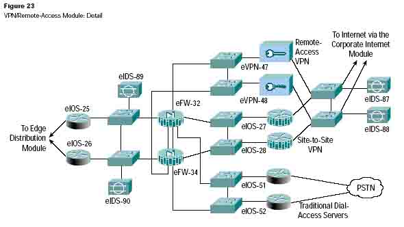
Threats Mitigated
-
Network topology discovery — Only Internet Key Exchange (IKE) and Encapsulating Security Payload (ESP) are allowed into this segment from the Internet
-
Password attack — OTP authentication reduces the likelihood of a successful password attack
-
Unauthorized access — Firewall services after packet decryption prevent traffic on unauthorized ports
-
Man-in-the-middle attacks — Mitigated through encrypted remote traffic
-
Packet sniffers — A properly configured switched infrastructure and encrypted data limit the effectiveness of sniffing
Attack Mitigation Roles for VPN/Remote-Access Module Design Guidelines
Resilience aside, the core requirement of this module is to have three separate external user services for authentication and termination. Because the traffic comes from different sources outside of the enterprise network, the decision was made to provide a separate interface on the firewall for each of these three services. The design considerations for each of these services are addressed below.
Remote-Access VPN
VPN traffic is forwarded from the corporate Internet module access routers, where it is first filtered at the egress point to the specific IP addresses and protocols that are part of the VPN services.
Remote-access VPN traffic will be addressed to one specific public address using the IKE (UDP 500) protocol, the ESP (IP 50) protocol, and UDP port 10000. IKE provides tunnel setup, ESP encrypts the data, and UDP 10000 is optionally used if ESP traffic is tunneled inside of UDP to get around remote-site firewalling restrictions or NAT.
Because the IKE connection is not completed until the correct authentication information is provided, this provides a level of deterrence for a potential attacker. As part of the extensions (draft RFCs) of IKE, XAUTH provides an additional user authentication mechanism before the remote user is assigned any IP parameters. The VPN concentrator is “connected” to the access control server on the management subnet via its management interface.
Strong passwords are provided via the OTP server.
Once authenticated, the remote user is given access by receiving IP parameters
using another extension of
IKE — MODCFG. In addition to an IP address and the location of name servers (DNS
and WINS), MODCFG provides authorization services to control the access of the remote user. For
example, in SAFE, users are prevented from enabling split tunneling, which forces them to access the Internet via the
corporate connection. The IPSec parameters that are being used are Triple DES (3DES) for encryption and SHA-HMAC
for data integrity. The hardware encryption modules in the VPN concentrator allow remote-access VPN
services to be scalably deployed to thousands of remote users. Following termination of the VPN tunnel, traffic is
sent through a firewall to help ensure that VPN users are appropriately filtered.
Secure management of this service is achieved by pushing all IPSec and security parameters to remote users from the central site. Additionally, connections to all management functions are on a dedicated management interface.
Dial-In Access Users
Traditional dial-in users are terminated on one of the two access routers with built-in modems. Once the Layer 1 connection is established between the user and the server, three-way Challenge Handshake Authentication Protocol (CHAP) is used to authenticate the user. As with the remote-access VPN service, the authentication, authorization, and accounting (AAA) and OTP servers are used to authenticate and provide passwords. Once authenticated, the users are provided with IP addresses from an IP pool through Point-to-Point Protocol (PPP).
The accounting function of AAA can be used for tracking user logins, logging failures, and assigning IP addresses. If the site’s access security policy calls for a high level of security, one-time passwords (strong authentication) can easily be implemented. The authorization feature of an access control server can be enforced to limit operations that users can do on routers and switches, and also to limit from what location the remote user can access the network (recommended in high-security environments).
Site-to-Site VPN
The VPN traffic associated with site-to-site connections consists of GRE tunnels protected by an IPSec protocol in transport mode using ESP. As in the remote-access case, the traffic that is forwarded from the corporate Internet module can be limited to the specific destination addresses on the two VPN routers and the source addresses expected from the remote sites. The ESP protocol and the IKE protocol will be the only two expected on this link.
GRE is used to provide a full-service routed link that will carry multiprotocol, routing protocol, and multicast traffic.
Because routing protocols (Enhanced Interior Gateway Routing Protocol [EIGRP] is being used between remote sites) can detect link failure, the GRE tunnel provides a resilience mechanism for the remote sites if they build two GRE connections, one to each of the central VPN routers. There are currently no mechanisms available to authenticate GRE tunnels between routers.
As with remote-access VPN, 3DES (optionally Advanced Encryption Standard [AES]) and SHA-HMAC are used for IKE and IPSec parameters to provide the maximum security with little effect on performance. IPSec hardware accelerators are used in the VPN routers. In highly secure environments, public key infrastructure (PKI) can be used for establishing authenticated IPSec tunnels.
The Rest of the Module
The traffic from these three services is aggregated by the firewall onto one private interface before being sent to the edge distribution module via a pair of routers. The firewall must be configured with the right type of constraining access control to allow only the appropriate traffic through to the inside interface of the firewall from each of the services. In addition to access control, the firewalls provide a point of auditing for all VPN traffic and an enforcement point for NIDS threat response. A pair of NIDS appliances is positioned at the public side of the module to detect any network reconnaissance activity targeted at the VPN termination devices. On this segment, only IPSec (IKE/ESP) traffic should be seen. Because the NIDS system cannot see inside the IPSec packets, any alarm on this network indicates a failure or compromise of the surrounding devices. As such, these alarms should be set to high severity levels. A second pair of NIDSs is positioned after the firewall to detect any attacks that made it through the rest of the module. All users crossing this segment should be bound to, or coming from, a remote location so that any shunning or TCP resets will only affect those users. This allows a more restrictive stance for the NIDS as opposed to the corporate Internet module, where some of the NIDS devices have the potential to shut out legitimate users if too loosely configured. See the “SAFE IDS Best Practices” document in the SAFE library for a more detailed description of how to tune the appliances in this module.
Alternatives
In VPN and authentication technology, many alternatives are available, depending on the requirements of the network. These alternatives are listed below for reference, but the details are not addressed in this document.
-
Smart-card and/or biometric authentication
-
Layer 2 Tunneling Protocol (L2TP) or Point-to-Point Tunneling Protocol (PPTP) remote-access VPN tunnels
-
Certificate authorities
-
IKE keep-alive resilience mechanism
-
Multiprotocol Label Switching (MPLS) VPNs
-
TCP-encapsulated VPNs
An alternative VPN design has been proposed that significantly increases the scalability of the VPN solution. This design adds Layer 3 switches as a routing distribution layer before the clear-text traffic is sent through the firewall.
Interested readers should refer to the “SAFE VPN: IPSec Virtual Private Networks in Depth” document in the SAFE library.
WAN Module
Rather than including all potential WAN designs, this module shows resilience and security for WAN termination.
Using Frame Relay encapsulation, traffic is routed between remote sites and the central site (Figures 25 and 26).
Primary Devices
-
Cisco IOS router — Using routing, access control, and QoS mechanisms
Threats Mitigated
-
IP spoofing — Mitigated through Layer 3 filtering
-
Unauthorized access — Simple access control on the router can limit the types of protocols to which branches have access
Attack Mitigation Roles for WAN Module Design Guidelines
The resilience is provided by the dual connection from the service provider, through the routers, and to the edge distribution module. Security is provided by using Cisco IOS Software security features. Input access lists are used to block all unwanted traffic from the remote branch.
Alternatives
Some organizations that are concerned about information privacy encrypt highly confidential traffic on their WAN links. Similar to site-to-site VPNs, you can use IPSec to achieve this information privacy.
E-Commerce/Data Center Module
The architectural model chosen for this data center supports a typical three-tier, secure e-commerce application (Figures 27-29). The same design principles presented here could be used to support multiple-tier applications as well. The primary purpose of this module is to provide a secure environment for an enterprise to safely conduct electronic transactions. To ensure reliability, redundancy, performance, and security, this module was built with the following attributes:
-
Full redundancy to provide minimum downtime or service disruptions.
-
A three-tier data center design. This allows an enterprise to separate and secure critical services. For the e-commerce application, the first tier is called the Web tier and houses the Web server and SSL termination portion of the architecture (this tier is sometimes called the e-commerce front end). The second tier is called the application tier and houses the servers that run back-end Web applications and source calls to the back-end database. The third tier (also called back-end) is known as the database tier and houses the database servers, which store critical data.
-
Defense in depth to ensure that transactions and interactions between the three tiers are as secure as possible.
E-Commerce Traffic Flow
Primary Devices
-
Web server — Acts as the primary user interface for the navigation of the e-commerce store
-
Application server — The platform for the applications required by the Web server
-
Database server — The critical information that is the heart of the e-commerce business implementation
-
Firewall — Governs communications between the levels of security and trust in the system
-
NIDS — Provides monitoring of network segments in the module
-
SSL-offload appliance — Provides SSL offload to free CPU cycles on the Web servers, increasing SSL application performance and allowing scalable deployment of security services
-
Content, caching, and load-balancing switches — Provide intelligent content switching, malicious URL blocking, and load balancing
-
Layer 2 and Layer 3 switches — Private VLANs protect them from network sniffing
Threats Mitigated
-
Unauthorized access — 802.1x authentication, stateful firewalling, and ACLs limit exposure to specific protocols and unauthorized network devices
-
Application-layer attacks — Attacks are mitigated through the use of IDSs
-
DoS — ISP filtering, black-hole routing, and rate limiting reduce (D)DoS potential Cisco Express Forwarding and uRPF can be used to reduce the impact on a Layer 3 switch CPU during a packet flooding attack
-
IP spoofing — RFCs 2827 and 1918 prevent locally originated spoofed packets and limit remote spoof attempts
-
Packet sniffers — A properly configured switched infrastructure HIPS and SSL appliance in the switch limits the effectiveness of sniffing
-
Network reconnaissance — Ports are limited to only what is necessary; ICMP is restricted
-
Trust exploitation — Private VLANs and firewalls ensure that communication flows only in the proper direction on the proper service
-
Port redirection — HIPS and firewall filtering limit exposure to these attacks
-
Malicious code executing on the server — Intrusion prevention software on servers and hosts
-
URL attacks — Known URL attacks can be blocked using technology available in load balancing or inWeb proxy inspection software or appliances
-
Routing disruption — Neighbor router authentication ensures that routing updates are valid and received only from trusted neighbors
-
Zero-day attacks — Host intrusion prevention (see Appendix C for a discussion on zero-day attack mitigation)
Attack Mitigation Roles for E-Commerce Module
Design Implementation Description
At the heart of the e-commerce module are two pairs of resilient firewalls that provide protection for the three levels of servers — Web, application, and database. Added protection is provided by the ISP edge routers at the ISP and the enterprise. The design is best understood by considering the traffic flow sequence and direction for a typical e-commerce transaction, although any application with any number of tiers could be supported.
The e-commerce customer initiates an HTTP connection to the Web server after receiving the IP address from a DNS server hosted at the ISP network. The DNS is hosted on a different network to reduce the amount of protocols required by the e-commerce application. The first set of firewalls must be configured to allow HTTP through to the addresses resolved by the DNS. The return traffic for this connection is allowed back, but there is no need for any communication initiated by the Web server back out to the Internet. The firewall should block this path in order to limit the options of hackers if they were to gain control of one of the Web servers. Ideally, if secure Web traffic was used, the firewall must also be configured to allow HTTPS to pass. As the user navigates the Website, certain link selections trigger theWeb server to initiate a request to the application server on the inside interface. This connection must be permitted by the first firewall, as well as the associated return traffic. As with the Web server, in most cases there is no reason for the application server to initiate a connection to the Web server or even out to the Internet, unless the application is using a Distributed Component Object Model (DCOM) application, or requires DNS. The user’s entire session runs over HTTP and SSL with no ability to communicate directly with the application server or the database server. In accordance, the firewall and any Layer 3 devices should be configured to ensure that traffic is not sourced from the application server or the back-end database server.
In the Web tier, the Web servers are load-balanced using Layers 4 through 7 load balancers. The load balancers are configured to block URLs that are not valid for theWeb applications found on that segment. The load balancers are implemented with full redundancy for maximum uptime.
The SSL accelerator device provides secure termination forWeb transactions and also offloads CPU cycles that would normally be required to implement SSL on the Web servers. The following traffic flow is expected when the user performs a Web transaction:
-
The client requesting the Web page is redirected to the SSL device by the load balancer. All subsequent client communications occurs between the client and the SSL device.
-
The SSL setup protocol takes place between the client and the SSL device
-
The SSL device establishes a communication channel with the load balancer.
-
The client sends an encrypted GET request to the SSL device.
-
The SSL device validates the request using the SSL protocol, decrypts the transaction, and forwards it to the load balancer using HTTP.
-
The load balancer establishes an HTTP connection with the Web server, then forwards the request to the Web server.
-
The Web server responds to the HTTP request and sends it back to the load balancer.
-
The load balancer sends the HTTP request to the SSL device.
-
The SSL device encrypts the requests and sends SSL back to the client.
The firewalls in the e-commerce/data center module allow only three specific communication paths, one for each tier of the data center — Web tier, application tier, and database tier. Each communication path has its own protocol. The firewall must block all other communication.
All servers must be fully protected — especially theWeb server, which is a publicly addressable host. The OS, database application, and Web server application must be patched to the latest software revisions. All servers in the e-commerce module should run antivirus and HIPS software. This will mitigate against most application-layer, primary, and secondary attacks, such as port redirection and root kits.
Beyond the Firewall
The e-commerce firewalls are initially protected by the customer edge router residing on the network edge, at the egress of the firewall. At the router egress point, toward the enterprise, the ISP can limit the traffic to the small number of protocols required for e-commerce, with a destination address of the Web servers only. Routing protocol updates and ICMP are required by the edge routers. All other traffic destined to or from the devices should be blocked. The ISP should implement rate limiting and black-hole routing as necessary, as specified in the “Networks Are Targets” section, in order to mitigate (D)DoS attacks. In addition, the ISP should implement RFC 1918, RFC 2827, and bogon filtering. Routing protocols are also authenticated to ensure that routes are not disrupted. Edge routers will typically require ICMP echo-reply, unreachable, and time exceeded to allow control messaging return traffic and troubleshooting.
On the enterprise premises, the initial router layer serves only as an interface to the ISP. The Layer 3 switch performs all of the network processing, as it has features offloaded to hardware processors. Layer 3 switches participate in the full BGP routing decision in order to determine which ISP has the better route to the particular destination, to provide verification filtering in keeping with the ISP filtering described above, to provide layered security, and, as an alternate configuration, to provide built-in IDS monitoring. Placing sensors in this location allows you to monitor the types of attempts made at breaching the external firewall. This is the front line for monitoring the spread of a contagion or attack originating from the Internet.
IDS sensors are deployed in each of the three tiers. Any alarms triggered by the IDS sensors should be investigated as a possible attack against the e-commerce environment. Refer to the SAFE library for IDS tuning best practices.
If the connection to the Internet exceeds the capacity of the IDS line card, you may need to look only at inboundWeb requests. While this will miss some HTTP alarm signatures (approximately 10 percent), it is better than looking at the entire stream in both directions, where many false positives would result from oversubscription. The other NIDS appliances behind the various interfaces of the firewall monitor the segments for any attacks that might have penetrated the first line of defense. For example, if theWeb server was compromised via an application-layer attack, the NIDS would detect invalid network activity by the Web tier. Similar to the corporate Internet module edge, false positives must be removed so that all true attack detections are treated with the correct level of priority. In fact, because only certain types of traffic exist on certain segments, you can tune the NIDS very tightly. Refer to the SAFE library for IDS tuning best practices.
From an application standpoint, the communications paths between the various layers (Web, application, and database) should be encrypted, transactional, and highly authenticated. For example, if the application accesses data from the database over some type of scripted interactive session (remote-procedure call [RPC], RSH (Remote Shell), FTP, Telnet, and so forth) a hacker in control of an application tier can use that script to initiate an application-layer attack. By employing secure communications, you can limit potential threats. Secure Web traffic (HTTPS) termination occurs in the Web tier after the firewall and before the Web servers. This allows the load balancer to maintain persistence with servers, and also significantly speeds up SSL transactions. Traffic after SSL termination will be in the clear, but will be secure because of the usage of private VLANs. IDS sensors are deployed on those private VLANs to make sure that there are no attack attempts masked by SSL tunneling.
The Layer 2 switches that support the various firewall segments in all three tiers of the e-commerce/data center module provide the ability to implement secure VLANs. This establishes a trust model that matches the desired traffic communication on a particular segment and eliminates all others. For example, there is usually no reason for one Web server to communicate with another Web server.
The management of the entire module is done completely out of band to minimize the risk of management traffic being intercepted on the production data network.
Alternatives
There are several variations on the primary design for tiering, applications, and placement of this module. Aside from listing the alternatives, further discussion is beyond the scope of this paper.
The main alternative to this deployment is colocating the entire system at an ISP. Although the design remains the same, there are two primary differences. The first is that bandwidth is generally greater to the ISP and uses a LAN connection. While not recommended, this potentially eliminates the need for the edge routers in the proposed design.
The additional bandwidth also creates different requirements for (D)DoS mitigation. The second difference is the connection back to the enterprise, which needs to be managed in a different way. Options include encryption and private lines. Using these technologies creates additional security considerations, depending on the location of the connections and their intended uses.
Another alternative is to use this module for applications other than e-commerce on the Internet edge. This data center could be deployed in virtually any location in the enterprise, including the Internet, intranet, or extranet, with a single tier (as in the server module) or multiple tiers as modeled above. When deploying on an intranet or extranet, Cisco recommends using the same security posture regardless of the placement of the data center in the new topology.
With the exception of (D)DoS attacks, which are more common in the Internet data center, the threats are the same.
For high security requirements, the use of multiple firewall types may be considered. This creates additional management overhead in duplicating policy on disparate systems. The goal of these designs is to keep vulnerability in one firewall from circumventing the security of the entire system. These types of designs tend to be very firewall-centric and do not adequately take advantage of IDSs and other security technologies to mitigate the risk of single firewall vulnerability.
Lab Module
The primary goal of the lab module is to provide a secure infrastructure that will protect both the lab and the enterprise hosting the lab from unexpected behavior caused by malicious or uncontrolled devices. In Figure 30, secure access is allowed from the building distribution module to the lab. Access may also be allowed from the lab to the corporate network and the Internet. Labs pose significant risks to network and host security because they often run untested and undebugged software and are spontaneously regulated by corporate security teams. This type of test environment can be a breeding ground for unexpected network problems caused by malicious software and activity.
Primary Devices
-
Terminal server — Provides access to the lab device consoles
-
Event logging server — Provides alarm aggregation for all NIDS, HIPS, and network devices in the secure lab backbone
-
DNS server — Name to address translations for all internal lab devices
-
Access control server — Controls access to all lab devices via TACACS+
-
NIDS module — Provides Layer 4 through Layer 7 monitoring of network segments
-
Firewall — Allows control of traffic flows between the lab environment and the enterprise network
-
Layer 2 switch (with private VLAN support) — Separates the lab environment from the lab secure backbone infrastructure and provides private VLANs within the lab infrastructure
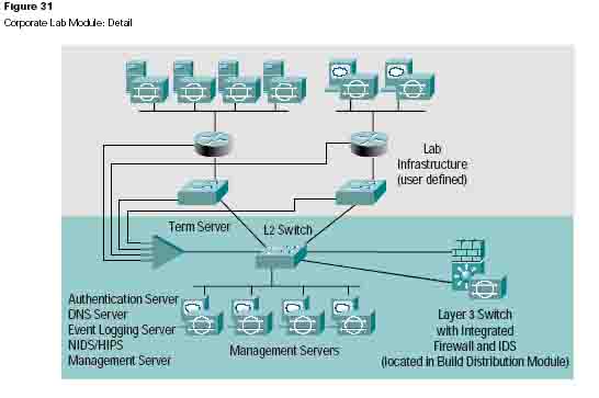
Threats Mitigated
-
Unauthorized access — Mitigated through filtering at the Layer 3 router and corporate firewall
-
Worm, virus, and Trojan horse attacks — Mitigated through HIPS and antivirus software
-
Password attacks — Limited services available to brute force attacks; OS and IDS software can detect the threat
-
DoS — Host intrusion using custom rules for rate limiting
-
IP spoofing — RFC 2827 and 1918 filtering at inside firewall
-
Packet sniffers — A properly configured switched infrastructure and HIPS limit exposure to packet sniffing
-
Network reconnaissance — IDS detects reconnaissance and protocols are filtered to limit effectiveness; IPS eliminates reconnaissance on hosts, and firewalls silently discard reconnaissance packets
-
Trust exploitation — Restrictive trust model and private VLANs limit trust-based attacks
-
Port redirection — Restrictive filtering and HIPSs limit attack
-
Root kit, virus, worm, and zero-day attacks — HIPS and antivirus software will circumvent these attacks
-
URL-based attacks — Mitigated through the use of HIPSs
Design Guidelines
A lab environment has many inherent security issues. Operating system and application patches are not usually enforced; many lab machines have test software that relies on operating systems that have not been standardized by the enterprise and authentication controls are typically not in use. In general, lab security best practices in an enterprise are encouraged, but not strictly enforced as they would be in the rest of an enterprise. The remainder of this module focuses on architecture and security recommendations that help to provide security in this type of environment.
The lab module is broken up into two sections separated by an integrated firewall in the Layer 3 switch of the building distribution module. The first module is the secure lab backbone; the second is the user-defined lab.
1. The secure lab backbone contains all of the security devices and management servers. It is assumed that the administrators in the lab will be different than the enterprise infosec group that governs security in the entire corporation. If an enterprise policy calls for collaborative management of the lab, it is possible to manage access and monitor attack alarms centrally or locally in the lab. Most likely, corporate infosec teams already have expertise in analyzing security alarm data.
2. Traditional lab devices are located in the user-defined lab infrastructure.
This design uses VLANs for segmentation. The firewalled VLANs allow the flexibility to add labs for
additional departments in the lab, and to keep them separate from other departments to mitigate spreading threats
or to secure sensitive data
and higher availability.
The secure backbone is comprised of a firewall, an IDS sensor, a terminal server, and a Layer 3 switch connecting the secure backbone to the rest of the lab infrastructure. Two Layer 3 switches in failover mode can be used to ensure high availability.
This design uses three servers and an event logger to support network services for the secure backbone of the lab. These servers are protected using HIPS software to mitigate primary and secondary host attacks.
1. A DNS server provides name resolution for internal lab devices
2. An event logger logs IDS, host intrusion events, syslog, and syslog messages
3. An authentication server handles local administration of lab access policies
4. A threat-response server reduces false IDS alarms
The firewall connects the lab to the enterprise network. It is configured only to allow traffic in and out as defined by the enterprise’s security policy. For instance, it is possible to connect to any of the lab devices in the enterprise by using a combination of stateful firewall and access control. The firewall can be used to authenticate traffic using cut-through proxy. If SSH access is required from the outside of the lab, the firewall proxy authentication should be used to validate user credentials. Ensure that remote management of lab systems is done securely and according to SAFE axioms. To enable access to the servers from the enterprise, consider remote console access software. Realize, however, that only in recent versions of such software were secure access methods provided. The filtering on the firewall should include anti-spoofing filters as described in RFC 2827. The IP addresses inside the lab are private and not part of the enterprise. DNS queries from inside the lab should be isolated to the lab and should not be allowed to transverse the firewall unless it is determined that the lab must have Internet or enterprise access.
The firewall splits the lab into secure zones. The “inside” zone is the lab management module and the DMZ zones segment the user-defined labs. The different departments or business functions can share the lab infrastructure but can achieve separation using VLAN functions and firewalls. To hide addresses, NAT is used to provide access between the lab and the corporate network. Authentication proxies should be used on the firewall to control and monitor access through the firewall to the enterprise or the Internet.
An IDS is used to monitor all lab traffic and to detect attacks. IDS alarms should be sent to the logging server or consolidated with enterprise-wide IDS alarms. Shunning could be considered, but given the uncontrolled lab environment, the administrative overhead will be significant and the potential for false positives is high. To ensure that hosts in the lab are not infected by malicious code, HIPS software is recommended in both the secure lab backbone and the user-defined lab.
Threat-response software can help to detect hosts that have been compromised in an attack. The software will automatically check IDS signatures and check systems to see if they have been compromised. It will help to reduce the number of false positives in IDS reporting, and will significantly reduce the manual work required to research network break-ins. Threat-response software can run in the server portion of the lab or it can run on a server in the enterprise management module.
The terminal server provides console access to all networking devices in the lab. The terminal server, as well as all other network devices, should be configured to use the lab backbone access control server to enforce strong authentication. If it is required to check user credentials against the corporate authentication server, then appropriate access must be configured on the firewall.
The access control server provides TACACS+ authentication services and ensures that all inbound and outbound devices accessing the lab are strongly authenticated.
The event-logging server is used to consolidate syslog, IDS, and IPS events to a single source. This provides the forensics necessary to identify, isolate, and recover from a host or network attack.
Alternatives
An alternative is to use security appliances instead of the integrated IDS and firewall modules used in this design. See Appendix D for a more in-depth discussion of trade-offs between integrated modules and standalone appliances.
Enterprise Options
The design process is often a series of trade-offs. This short subsection of the document highlights some of the high-level options that a network designer could implement if faced with tighter budget constraints. Some of these trade-offs occur at the module level, while others occur at the component level.
A first option is to collapse the distribution modules into the core module. This reduces the number of Layer 3 switches by 50 percent. The cost savings would be traded for performance requirements in the core of the network, and for flexibility to implement all of the distribution security filtering.
A second option is to merge the VPN/remote-access module with the corporate Internet module. Their structure is very similar, with a pair of firewalls at the heart of the module, surrounded by NIDS appliances. This may be possible without loss of certain functions if the performance of the components matches the combined traffic requirements of the modules, and if the firewall has enough interfaces to accommodate the different services. Keep in mind that as functions are aggregated to single devices, the potential for human error increases. Some organizations go even further and include the e-commerce functions in the corporate Internet/VPN module. The authors feel that the risk of doing this far outweighs any cost savings unless the e-commerce needs are minimal. Separation of e-commerce traffic from general Internet traffic allows the e-commerce bandwidth to be better optimized by allowing the ISP to place more restrictive filtering and rate-limiting technology to mitigate against DDoS attacks.
A third option is to eliminate some of the NIDS appliances. Depending on your operational threat response strategy, you might need fewer NIDS appliances. This number is also affected by the amount of host IDSs deployed, because this might reduce the need for NIDS in certain locations. This is discussed, where appropriate, in the specific modules.
A fourth option to consider is integrated switch modules vs. standalone appliances. This can reduce the total number of devices and provide the flexibility of incremental bandwidth growth. See Appendix D for a more in-depth discussion on this solution.
Clearly, network design is not an exact science. Choices must always be made based on the specific requirements facing the designer. The authors are not proposing that any designer would implement this architecture verbatim; designers are encouraged to make educated choices about network security grounded in this proven implementation.
Migration Strategies
SAFE is a guide for implementing security on the enterprise network. It is not meant to serve as a security policy for any enterprise networks, nor is it meant to serve as the all-encompassing design for providing full security for all existing networks. Rather, SAFE is a template that enables network designers to consider how they design and implement their enterprise networks in order to meet their security requirements.
Establishing a security policy should be the first activity when migrating the network to a secure infrastructure. Basic recommendations for a security policy can be found in Appendix B. After the policy is established, the network designer should consider the security axioms described in the first section of this document and see how they provide more detail to map the policy on the existing network infrastructure.
There is enough flexibility in the architecture and enough detail about the design considerations to enable the SAFE architecture elements to be adapted to most enterprise networks. For example, in the VPN/remote-access module, the various flows of traffic from public networks are each given a separate pair of terminating devices and a separate interface on the firewall. The VPN traffic could be combined in one pair of devices, if the load requirements permitted it and the security policy was the same for both types of traffic. On another network, the traditional dial-in and remote-access VPN users might be allowed directly into the network because the security policy puts enough trust in the authentication mechanisms that permit the connection to the network in the first place.
SAFE allows the designer to address the security requirements of each network function almost independently of each other. Each module is generally self-contained and assumes that any interconnected module is only at a basic security level. This allows network designers to use a phased approach to securing the enterprise network. They can address securing the most critical network functions as determined by the policy, without redesigning the entire network. The exception to this is the management module. During the initial SAFE implementation, the management module should be implemented in parallel with the first module. As the rest of the network is migrated, the management module can be connected to the remaining locations.
Appendix A: Validation Lab
A reference for SAFE implementation exists to validate the capabilities and features described in this document. This appendix details the configurations of the specific devices within each module, as well as the overall guidelines for general device configuration. Following are configuration snapshots from the live devices in the lab.
The authors do not recommend applying these configurations directly to a production network.
Overall Guidelines
The configurations presented here correspond in part to the SAFE axioms presented earlier in this document. Please, contact the representative named at the foot of this White Paper for explanations.
Routers
Here are the basic configuration options present on nearly all routers in the SAFE lab:
! turn off unnecessary services
!
no service pad
no ip domain-lookup
no cdp run
no ip http server
no ip source-route
no service finger
no ip bootp server
no service udp-small-servers
no service tcp-small-servers
service tcp-keepalives-in
service tcp-keepalives-out
service sequence-numbers!
!turn on logging and snmp!
service timestamps debug datetime msec localtime show-timezone
service timestamps log datetime msec localtime show-timezone
logging 192.168.253.56
logging 192.168.253.51
logging buffered 51200 debugging
logging console critical
snmp-server community Txo~QbW3XM ro 98!
!Turn on generalized DDoS mitigation assistance!
ip tcp synwait-time 10
scheduler allocate 4000 1000!
!set passwords and access restrictions!
service password-encryption
enable secret %Z<)|z9~zq
access-list 99 permit 192.168.253.0 0.0.0.255
access-list 99 deny any log
access-list 98
access-list 98
line vty 0 4
access-class 99
login
password 0 X)[^
exec-timeout 2
line con 0
login
password 0 X)[^
exec-timeout 2
line aux 0
transport input
password 0 X)[^
no exec
exit
banner motd #
This is a private system operated for and by Cisco VSEC BU.
Authorization from Cisco VSEC management is required to use this system.
Use by unauthorized persons is prohibited.#!
!Turn on NTP!
clock timezone PST -8
clock summer-time PST recurring
ntp authenticate
ntp authentication-key 1 md5 -UN&/6[oh6
ntp trusted-key 1
ntp access-group peer 96
ntp server 192.168.254.57 key 1
access-l 96 permit host 192.168.254.57
access-l 96 deny any log!
!Turn on AAA!
aaa new-model
aaa authentication login default tacacs+ enable
aaa authentication login no_tacacs line
aaa authorization exec tacacs+
aaa authorization network tacacs+
aaa accounting network start-stop tacacs+
aaa accounting exec start-stop tacacs+
tacacs-server host 192.168.253.54 single
tacacs-server key SJj)j~t]6-
line con 0
login authentication no_tacacs
The following configuration snapshot defines the Open Shortest Path First (OSPF) authentication and filtering parameters for all OSPF routers within the network. Note the Message Digest Algorithm 5 (MD5) authentication, as well as the distribution lists ensuring the OOB network is not advertised.
interface Vlan13
ip address 10.1.13.3 255.255.255.0
ip ospf authentication message-digest
ip ospf message-digest-key 1 md5 7 024D105641521F0A7E
ip ospf priority 3!
router ospf 1
area 0 authentication message-digest
network 10.1.0.0 0.0.255.255 area 0
distribute-list 1 out
distribute-list 1 in!
access-list 1 deny 192.168.0.0 0.0.255.255
access-list 1 permit any
The following configuration snapshot defines the access control present on all OOB interfaces throughout the network. Keep in mind that this is in addition to the private VLANs that block access between managed host IP addresses.
interface FastEthernet1/0
ip address 192.168.254.15 255.255.255.0
ip access-group 101 in
ip access-group 102 out
no cdp enable!
access-list 101 permit icmp any any
access-list 101 permit tcp 192.168.253.0 0.0.0.255 host 192.168.254.15
established
access-list 101 permit udp 192.168.253.0 0.0.0.255 host 192.168.254.15 gt 1023
access-list 101 permit tcp 192.168.253.0 0.0.0.255 host 192.168.254.15 eq Telnet
access-list 101 permit udp host 192.168.253.51 host 192.168.254.15 eq snmp
access-list 101 permit udp host 192.168.253.53 host 192.168.254.15 eq tftp
access-list 101 permit udp host 192.168.254.57 host 192.168.254.15 eq ntp
access-list 101 deny ip any any log
access-list 102 deny ip any any log
Switches
Here is the base security configuration present on nearly all Cisco Catalyst� OS switches in the SAFE lab. Cisco IOS Softwate-based switches use a configuration nearly identical to the router configuration.
!
!Turn on NTP
!
set timezone PST -8
set summertime PST
set summertime recurring
set ntp authentication enable
set ntp key 1 trusted md5 -UN&/6[oh6
set ntp server 192.168.254.57 key 1
set ntp client enable
!
! turn off un-needed services
!
set cdp disable
set ip http server disable
!
!turn on logging and snmp
!
set logging server 192.168.253.56
set logging server 192.168.253.51
set logging timestamp enable
set snmp community read-only Txo~QbW3XM
set ip permit enable snmp
set ip permit 192.168.253.51 snmp
!
!Turn on AAA
!
set tacacs server 192.168.253.54 primary
set tacacs key SJj)j~t]6-
set authentication login tacacs enable telnet
set authentication login local disable Telnet
set authorization exec enable tacacs+ deny Telnet
set accounting exec enable start-stop tacacs+
set accounting connect enable start-stop tacacs+
!
!set passwords and access restrictions
!
set banner motd <c>
This is a private system operated for and by Cisco VSEC BU.
Authorization from Cisco VSEC management is required to use this system.
Use by unauthorized persons is prohibited.
<c>
!console password is set by 'set password'
!enter old password followed by new password
!console password = X)[^j+#T98
!
!enable password is set by 'set enable'
!enter old password followed by new password
!enable password = %Z<)|z9~zq
!
!the following password configuration only works the first time
!
set password
X)[^j+#T98
X)[^j+#T98
set enable
cisco
%Z<)|z9~zq
%Z<)|z9~zq
!
!the above password configuration only works the first time
!
set logout 2
set ip permit enable Telnet
set ip permit 192.168.253.0 255.255.255.0 Telnet
In this proof of concept, lab hosts were patched with the latest fixes. Auto-update was enabled on all Windows and Linux hosts to ensure that patches were applied in a timely manner. Host intrusion prevention software was applied to all critical hosts and servers in the SAFE reference lab.
Management Module
Products Used
-
Cisco Catalyst 3500 Series XL Layer 2 switches (all switching)
-
Cisco PIX� Firewall
-
Cisco 2511 Router (terminal servers)
-
Cisco Secure IDS Sensor
-
RSA SecureID OTP Server
-
Cisco Secure Access Control Server
-
CiscoWorks 2000
-
Cisco Secure Policy Manager
-
Cisco IDS Host Sensor
-
netForensics syslog analysis tool
Cisco PIX Firewall
The following configuration sets the parameters and characteristics for Cisco PIX interface devices:
interface ethernet0 auto
interface ethernet1 auto
interface ethernet2 auto
interface ethernet3 auto
nameif ethernet0 outside security0
nameif ethernet1 inside security100
nameif ethernet2 managed_devices
security10
nameif ethernet3 remote_admin security20
enable password n.LMIanJG5.chDKZ encrypted
mtu outside 1500
mtu inside 1500
mtu managed_devices 1500
mtu remote_admin 1500
ip address outside 10.1.20.57 255.255.255.0
ip address inside 192.168.253.57 255.255.255.0
ip address managed_devices 192.168.254.57 255.255.255.0
ip address remote_admin 192.168.252.57 255.255.255.0
access-group outside in interface outside
access-group managed_devices in interface managed_devices
access-group remote_admin in interface remote_admin
access-group inside in interface inside
The following commands set up address translation and general connection controls such as ARP and address translation:
arp timeout 14400
global (outside) 1 10.1.20.100-10.1.20.149
nat (inside) 0 access-list nat_mgmt
nat (inside) 1 0.0.0.0 0.0.0.0 0 0
nat (managed_devices) 1 0.0.0.0 0.0.0.0 0 0
nat (remote_admin) 1 0.0.0.0 0.0.0.0 0 0
static (inside,managed_devices) 192.168.253.0 192.168.253.0 netmask
255.255.255.0 0 0
static (inside,remote_admin) 192.168.253.0 192.168.253.0 netmask 255.255.255.0 0
0
static (remote_admin,managed_devices) 192.168.252.0 192.168.252.0 netmask
255.255.255.0
0 0
static (inside,outside) 10.1.20.150 192.168.253.150 dns netmask 255.255.255.255
10000
10000
static (inside,outside) 10.1.20.54 192.168.253.54 netmask 255.255.255.255 0 0
static (inside,outside) 10.1.20.58 192.168.253.58 netmask 255.255.255.255 0 0
timeout xlate 3:00:00
timeout conn 1:00:00 half-closed 0:10:00 udp 0:02:00 rpc 0:10:00 h225
1:00:00
timeout h323 0:05:00 mgcp 0:05:00 sip 0:30:00 sip_media 0:02:00
timeout uauth 0:05:00 absolute
route outside 0.0.0.0 0.0.0.0 10.1.20.8 1
route outside 172.16.152.118 255.255.255.255 10.1.20.8 1
access-list nat_mgmt permit ip 192.168.253.0 255.255.255.0 192.168.254.0
255.255.255.0
access-list nat_mgmt permit ip 192.168.253.0 255.255.255.0 192.168.252.0
255.255.255.0
access-list nat_mgmt permit ip 192.168.253.0 255.255.255.0 172.16.224.0
255.255.255.0
access-list nat_mgmt permit ip 192.168.253.0 255.255.255.0 172.16.152.0
255.255.255.0
access-list nat_mgmt deny ip 192.168.253.0 255.255.255.0 any
The following configuration sets up logging for the Cisco PIX device:
logging on
logging timestamp
logging trap warnings
logging history warnings
logging facility 23
logging host inside 192.168.253.52
logging host inside 192.168.253.56
The following configuration sets up management for out-of-band and IPSec-protected in-band management:
http server enable
http 192.168.253.0 255.255.255.0 inside
snmp-server host inside 192.168.253.51
no snmp-server location
no snmp-server contact
snmp-server community xxxx215327gfsw87%%%
no snmp-server enable traps
Telnet no caps for telnet 192.168.253.0 255.255.255.0 inside
Telnet 172.16.224.23 255.255.255.255 inside
Telnet 172.16.224.23 255.255.255.255 managed_devices
Telnet 172.16.224.23 255.255.255.255 remote_admin
Telnet timeout 5
The following configuration defines protocols that will be inspected beyond Layer 4 before packet processing:
fixup protocol dns maximum-length 512
fixup protocol ftp 21
fixup protocol h323 h225 1720
fixup protocol h323 ras 1718-1719
fixup protocol http 80
fixup protocol ils 389
fixup protocol rsh 514
fixup protocol rtsp 554
fixup protocol sip 5060
fixup protocol sip udp 5060
fixup protocol skinny 2000
fixup protocol smtp 25
fixup protocol sqlnet 1521
fixup protocol tftp 69
The following configuration sets up the encrypted in-band network management:
crypto ipsec transform-set mgmt esp-3des esp-sha-hmac
crypto map mgmt 10 ipsec-isakmp
crypto map mgmt 10 match address mgmt_peer1
crypto map mgmt 10 set peer 172.16.224.23
crypto map mgmt 10 set transform-set mgmt
crypto map mgmt 20 ipsec-isakmp
crypto map mgmt 20 match address mgmt_peer2
crypto map mgmt 20 set peer 172.16.224.24
crypto map mgmt 20 set transform-set mgmt
crypto map mgmt 30 ipsec-isakmp
crypto map mgmt 30 match address mgmt_peer3
crypto map mgmt 30 set peer 10.1.158.118
crypto map mgmt 30 set transform-set mgmt
crypto map mgmt 40 ipsec-isakmp
crypto map mgmt 40 match address mgmt_peer4
crypto map mgmt 40 set peer 10.1.158.119
crypto map mgmt 40 set transform-set mgmt
crypto map mgmt interface outside
isakmp enable outside
isakmp key ******** address 172.16.224.23 netmask 255.255.255.255 no-xauth
no-config-mode
isakmp key ******** address 172.16.224.24 netmask 255.255.255.255 no-xauth no-config-mode
isakmp key ******** address 10.1.158.118 netmask 255.255.255.255 no-xauth no-config-mode
isakmp key ******** address 10.1.158.119 netmask 255.255.255.255 no-xauth no-config-mode
isakmp identity address
isakmp keepalive 10
isakmp policy 10 authentication pre-share
isakmp policy 10 encryption 3des
isakmp policy 10 hash sha
isakmp policy 10 group 2
isakmp policy 10 lifetime 86400
access-list mgmt_peer1 permit ip 192.168.253.0 255.255.255.0 host
172.16.224.23
access-list mgmt_peer1 permit ip 10.1.120.0 255.255.255.0 host 172.16.224.23
access-list mgmt_peer1 permit udp 192.168.254.0 255.255.255.0 host 172.16.224.23
access-list mgmt_peer2 permit ip 192.168.253.0 255.255.255.0 host 172.16.224.24
access-list mgmt_peer2 permit ip 10.1.120.0 255.255.255.0 host 172.16.224.24
access-list mgmt_peer2 permit udp 192.168.254.0 255.255.255.0 host 172.16.224.24
access-list mgmt_peer3 permit ip 192.168.253.0 255.255.255.0 host 172.16.152.118
access-list mgmt_peer3 permit icmp 192.168.253.0 255.255.255.0 host
172.16.152.118
access-list mgmt_peer4 permit ip 192.168.253.0 255.255.255.0 host 172.16.152.119
access-list mgmt_peer4 permit icmp 192.168.253.0 255.255.255.0 host
172.16.152.119
AAA authentication commands:
aaa-server TACACS+ protocol tacacs+
aaa-server TACACS+ (inside) host 192.168.253.54 SJj)j~t]6- timeout 10
aaa-server RADIUS protocol radius
aaa-server LOCAL protocol local
aaa authentication Telnet console TACACS+
aaa authentication http console TACACS+
The following configuration defines inbound access control from the managed host network. Port 45000 is for CiscoSecure IDS and SSL is for Cisco Security Agent (the Cisco HIPS):
access-list managed_devices permit udp 192.168.254.0 255.255.255.0 host
192.168.253.56 eq
syslog
access-list managed_devices permit udp 192.168.254.0 255.255.255.0 host
192.168.253.58 eq
45000
access-list managed_devices permit tcp 192.168.254.0 255.255.255.0 host
192.168.253.58 eq
https
access-list managed_devices permit udp 192.168.254.0 255.255.255.0 host
192.168.253.53 eq
tftp
access-list managed_devices permit udp 192.168.254.0 255.255.255.0 host
192.168.254.57 eq
ntp
access-list managed_devices permit tcp 192.168.254.0 255.255.255.0 host
192.168.253.54 eq
tacacs
access-list managed_devices permit udp 192.168.254.0 255.255.255.0 host
192.168.253.54 eq
radius
access-list managed_devices permit udp 192.168.254.0 255.255.255.0 host
192.168.253.52 eq
syslog
access-list managed_devices permit tcp 192.168.254.0 255.255.255.0 host
192.168.253.53 eq
ftp
access-list managed_devices deny udp any any eq netbios-ns
access-list managed_devices deny udp any any eq netbios-dgm
access-list managed_devices permit udp 192.168.254.0 255.255.255.0 host
192.168.253.54 eq
1812
access-list managed_devices permit udp 192.168.254.0 255.255.255.0 host
192.168.253.54 eq
1813
The following configuration defines inbound access control from the management host network:
access-list inside permit tcp 192.168.253.0 255.255.255.0 host 192.168.253.57 eq
Telnet
access-list inside permit tcp host 192.168.253.54 255.255.255.0 eq tacacs host
192.168.253.57
access-list inside permit tcp 192.168.253.0 255.255.255.0 192.168.254.0
255.255.255.0 eq
Telnet
access-list inside permit tcp 192.168.253.0 255.255.255.0 any eq www
access-list inside permit tcp 192.168.253.0 255.255.255.0 any eq https
access-list inside
permit tcp 192.168.253.0 255.255.255.0 any eq ftp access-list inside permit tcp
192.168.253.0 255.255.255.0 192.168.254.0 255.255.255.0 eq https
access-list inside permit tcp 192.168.253.0 255.255.255.0 192.168.254.0
255.255.255.0 eq
ssh
access-list inside permit tcp 192.168.253.0 255.255.255.0 host 192.168.252.110
eq https
access-list inside permit udp host 192.168.253.50 192.168.254.0 255.255.255.0 eq
45000
access-list inside permit tcp host 192.168.253.50 192.168.254.0 255.255.255.0 eq
5000
access-list inside permit udp host 192.168.253.51 192.168.254.0 255.255.255.0 eq
snmp
access-list inside permit udp host 192.168.253.53 gt 1023 host 192.168.253.57 gt
1023
access-list inside permit udp 192.168.253.0 255.255.255.0 host 192.168.254.57 eq
ntp
access-list inside permit icmp 192.168.253.0 255.255.255.0 host 172.16.224.23
access-list inside permit icmp 192.168.253.0 255.255.255.0 host 172.16.224.24
access-list inside permit tcp 192.168.253.0 255.255.255.0 host 172.16.224.23 eq
Telnet
access-list inside permit tcp 192.168.253.0 255.255.255.0 host 172.16.224.24 eq
Telnet
access-list inside permit tcp host 192.168.253.54 host 10.1.70.120 eq ssh
access-list
inside permit tcp host 192.168.253.54 host 10.1.70.121 eq ssh access-list inside
permit
tcp host 192.168.253.54 host 10.1.80.122 eq ssh access-list inside permit tcp
host
192.168.253.54 host 10.1.80.123 eq ssh access-list inside permit udp host
192.168.253.51
host 172.16.224.23 eq snmp
access-list inside permit udp host 192.168.253.51 host 172.16.224.24 eq snmp
access-list inside permit udp host 192.168.253.77 host 172.16.224.23 eq snmp
access-list inside permit udp host 192.168.253.77 host 172.16.224.24 eq snmp
access-list inside permit udp host 192.168.253.78 host 172.16.224.23 eq snmp
access-list inside permit udp host 192.168.253.78 host 172.16.224.24 eq snmp
access-list inside permit udp host 192.168.253.79 host 172.16.224.23 eq snmp
access-list inside permit udp host 192.168.253.79 host 172.16.224.24 eq snmp
access-list inside permit udp 192.168.253.0 255.255.255.0 host 10.1.11.50 eq
domain
access-list inside permit tcp host 192.168.253.150 object-group wlse-managed-aps
object-group wlse-tcp-mgmt
access-list inside permit udp host 192.168.253.150 object-group wlse-managed-aps
object-group wlse-udp-mgmt
object-group network wlse-managed-aps
These are access points that are managed by the Wireless LAN Solution Engine:
network-object 10.1.70.120 255.255.255.255
network-object 10.1.70.121 255.255.255.255
network-object 10.1.80.122 255.255.255.255
network-object 10.1.80.123 255.255.255.255
object-group service wlse-tcp-mgmt tcp
description WLSE TCP Based Management Traffic
port-object eq ssh
port-object eq www
object-group service wlse-udp-mgmt udp
description WLSE UDP Based Management Traffic
port-object eq snmp
access-list inside permit tcp 192.168.253.0 255.255.255.0 host 172.16.152.118 eq
Telnet
- no caps
access-list inside permit tcp 192.168.253.0 255.255.255.0 host 172.16.152.119 eq
Telnet
The following configuration defines inbound access control from the production network:
access-list outside permit icmp host 172.16.224.23 192.168.253.0 255.255.255.0
echo-reply
access-list outside permit icmp host 172.16.224.24 192.168.253.0 255.255.255.0
echo-reply
access-list outside permit icmp host 172.16.152.118 192.168.253.0 255.255.255.0
echo-reply
access-list outside permit icmp host 172.16.152.119 192.168.253.0
255.255.255.0
echo-reply
access-list outside permit udp host 172.16.224.23 host 192.168.253.56 eq syslog
access-list outside permit udp host 172.16.224.24 host 192.168.253.56 eq syslog
access-list outside permit udp host 172.16.152.118 host 192.168.253.56 eq syslog
access-list outside permit udp host 172.16.152.119 host 192.168.253.56 eq syslog
access-list outside permit udp host 172.16.224.23 host 192.168.253.52 eq syslog
access-list outside permit udp host 172.16.224.24 host 192.168.253.52 eq syslog
access-list outside permit udp host 172.16.152.118 host 192.168.253.52 eq syslog
access-list outside permit udp host 172.16.152.119 host 192.168.253.52 eq syslog
access-list outside permit udp host 172.16.224.23 host 192.168.253.53 eq tftp
access-list outside permit udp host 172.16.224.24 host 192.168.253.53 eq tftp
access-list outside permit udp host 172.16.152.118 host 192.168.253.53 eq tftp
access-list outside permit udp host 172.16.152.119 host 192.168.253.53 eq tftp
access-list outside permit udp host 172.16.224.23 host 192.168.254.57 eq ntp
access-list outside permit udp host 172.16.224.24 host 192.168.254.57 eq ntp
access-list outside permit udp host 172.16.152.118 host 192.168.254.57 eq ntp
access-list outside permit udp host 172.16.152.119 host 192.168.254.57 eq ntp
access-list outside permit tcp host 172.16.224.23 host 192.168.253.54 eq tacacs
access-list outside permit tcp host 172.16.224.24 host 192.168.253.54 eq tacacs
access-list outside permit tcp host 172.16.152.118 host 192.168.253.54 eq tacacs
access-list outside permit tcp host 172.16.152.119 host 192.168.253.54 eq tacacs
access-list outside permit tcp 10.0.0.0 255.0.0.0 host 10.1.20.58 eq https
Core Module
Figure 33 shows the detail in the core module.
Products Used
-
Cisco Catalyst 6500 Series Layer 3 switches
Building Distribution Module
Figure 34 shows the detail in the building distribution module.
Products Used
-
Cisco Catalyst 6500 Series Layer 3 switches
The following configuration snapshot defines the Layer 3 access control between subnets in this module. VLAN 5defines the marketing subnet, VLAN 6 defines the R&D subnet, VLAN 7 defines the marketing IP phones, andVLAN 8 defines the R&D IP phones.
interface Vlan5
ip address 10.1.5.5 255.255.255.0
ip access-group 105 in
!
interface Vlan6
ip address 10.1.6.5 255.255.255.0
ip access-group 106 in
!
interface Vlan7
ip address 10.1.7.5 255.255.255.0
ip access-group 107 in
!
interface Vlan8
ip address 10.1.8.5 255.255.255.0
ip access-group 108 in
!
access-list 105 deny ip 10.1.5.0 0.0.0.255 10.1.6.0 0.0.0.255
access-list 105 deny ip 10.1.5.0 0.0.0.255 10.1.7.0 0.0.0.255
access-list 105 deny ip 10.1.5.0 0.0.0.255 10.1.8.0 0.0.0.255
access-list 105 deny ip 10.1.5.0 0.0.0.255 10.1.16.0 0.0.0.255
access-list 105 permit ip 10.1.5.0 0.0.0.255 any
access-list 105 deny ip any any log
access-list 106 deny ip 10.1.6.0 0.0.0.255 10.1.5.0 0.0.0.255
access-list 106 deny ip 10.1.6.0 0.0.0.255 10.1.7.0 0.0.0.255
access-list 106 deny ip 10.1.6.0 0.0.0.255 10.1.8.0 0.0.0.255
access-list 106 deny ip 10.1.6.0 0.0.0.255 10.1.15.0 0.0.0.255
access-list 106 deny ip 10.1.6.0 0.0.0.255 10.1.16.0 0.0.0.255
access-list 106 permit ip 10.1.6.0 0.0.0.255 any
access-list 106 deny ip any any log
access-list 107 permit ip 10.1.7.0 0.0.0.255 10.1.8.0 0.0.0.255
access-list 107 permit ip 10.1.7.0 0.0.0.255 10.1.16.0 0.0.0.255
access-list 107 permit ip 10.1.7.0 0.0.0.255 host 10.1.11.50
access-list 107 deny ip any any log
access-list 108 permit ip 10.1.8.0 0.0.0.255 10.1.7.0 0.0.0.255
access-list 108 permit ip 10.1.8.0 0.0.0.255 10.1.16.0 0.0.0.255
access-list 108 permit ip 10.1.8.0 0.0.0.255 host 10.1.11.50
access-list 108 deny ip any any log
Building Access Module
Figure 35 shows the detail in the building access module.
Products Used
-
Cisco Catalyst 3550 Series XL Layer 2 switches
-
Cisco IP Phone
The following configuration snapshot shows some of the VLAN settings on the Layer 2 switches in this module. Notice that unneeded ports are disabled and set to a nonroutable VLAN (999). Also, trunking is turned off on all ports except those connecting to IP phones that use trunking for VLAN separation between a phone and a workstation. Ports that are connected to user workstations have 802.1x activated.
interface FastEthernet0/1
switchport access vlan 999
no ip address
shutdown
no cdp enable
!
interface FastEthernet0/2
switchport access vlan 999
no ip address
shutdown
no cdp enable
!
interface FastEthernet0/3
switchport access vlan 999
no ip address
shutdown
no cdp enable
!
interface FastEthernet0/4
switchport trunk allowed vlan 1,5-8,70-73,80-83,1002-1005
no ip address
no cdp enable
!
interface FastEthernet0/5
switchport mode access
no ip address
no cdp enable
dot1x port-control auto
spanning-tree portfast
!
interface FastEthernet0/6
switchport mode access
no ip address
no cdp enable
dot1x port-control auto
spanning-tree portfast
!
interface FastEthernet0/7
switchport access vlan 6
switchport mode dynamic desirable
no cdp enable
!
interface FastEthernet0/8
switchport access vlan 6
switchport mode dynamic desirable
no cdp enable
Server Module
Figure 36 shows the detail in the server module.
Products Used
-
Cisco Catalyst 6500 Series Layer 3 switches
-
Cisco Catalyst 6500 Series Intrusion Detection Blade
-
Cisco CallManager
-
Cisco IDS
EL3SW-1 and 2
The following configuration sets the private VLAN mappings for several of the ports within the same VLAN. This configuration prevents the internal e-mail server from communicating with the corporate server.
! CAT OS Config
!
#private vlans
set pvlan 11 437
set pvlan 11 437 3/3-4,3/14
set pvlan mapping 11 437 15/1
!
! MSFC Config
!
interface Vlan11
ip address 10.1.11.1 255.255.255.0
ip access-group 111 in
no ip redirects
The following configuration sets the interface filtering on several of the interfaces in this module (including RFC 2827 filtering):
interface Vlan11
ip address 10.1.11.1 255.255.255.0
ip access-group 111 in
!
interface Vlan15
ip address 10.1.15.1 255.255.255.0
ip access-group 115 in
!
interface Vlan16
ip address 10.1.16.1 255.255.255.0
ip access-group 116 in
ip access-group 126 out
!
access-list 111 permit ip 10.1.11.0 0.0.0.255 any
access-list 111 deny ip any any log
access-list 115 permit ip 10.1.15.0 0.0.0.255 any
access-list 115 deny ip any any log
access-list 116 permit ip 10.1.16.0 0.0.0.255 10.1.7.0 0.0.0.255
access-list 116 permit ip 10.1.16.0 0.0.0.255 10.1.8.0 0.0.0.255
access-list 116 permit ip 10.1.16.0 0.0.0.255 10.1.11.0 0.0.0.255
access-list 116 deny ip any any log
access-list 126 permit ip 10.1.7.0 0.0.0.255 10.1.16.0 0.0.0.255
access-list 126 permit ip 10.1.8.0 0.0.0.255 10.1.16.0 0.0.0.255
access-list 126 permit ip 10.1.11.0 0.0.0.255 10.1.16.0 0.0.0.255
The following configuration sets up the capture port for the Cisco Catalyst 6000 Series IDS module:
#module 4 : 2-port Intrusion Detection System
set module name 4
set module enable 4
set vlan 1 4/1
set vlan 99 4/2
set port name 4/1 Sniff-4
set port name 4/2 CandC-4
set trunk 4/1 nonegotiate dot1q 1-1005,1025-4094
set security acl capture-ports 4/1
Edge Distribution Module
Figure 37 shows the detail in the edge distribution module.
Products Used
-
Cisco Catalyst 6500 Series Layer 3 switches
Corporate Internet Module
Figure 38 shows the detail in the corporate Internet module.
Products Used
-
Cisco PIX Firewall
-
Cisco Secure IDS Sensor
-
Cisco Catalyst 3500 Series Layer 2 switches
-
Cisco 7100 Series VPN Router
-
Cisco IDS Host Sensor
-
WebSense URL Filtering Server
-
Cisco Application and Content Networking System (ACNS) cache engine
EPIX-31 and 33
This configuration snapshot details the access control in place on the Cisco PIX firewall. The name of the access list denotes the location the inbound ACL is placed. “In” is inbound, “out” is outbound, “pss” is the public services segment (DMZ), “url” is the content filtering segment, and “mgmt” is the OOB interface.
access-list out deny ip any 192.168.254.0 255.255.255.0
access-list out deny ip any 192.168.253.0 255.255.255.0
access-list out permit icmp any any echo-reply
access-list out permit tcp any host 172.16.225.52 eq www
access-list out permit tcp any host 172.16.225.52 eq ftp
access-list out permit tcp any host 172.16.225.50 eq smtp
access-list out permit udp any host 172.16.225.51 eq domain
access-list out permit esp host 172.16.224.23 host 172.16.224.57
access-list out permit esp host 172.16.224.24 host 172.16.224.57
access-list out permit udp host 172.16.224.23 host 172.16.224.57 eq isakmp
access-list out permit udp host 172.16.224.24 host 172.16.224.57 eq isakmp
access-list in deny ip any 192.168.254.0 255.255.255.0
access-list in deny ip any 192.168.253.0 255.255.255.0
access-list in permit icmp any any echo
access-list in permit udp host 10.1.11.50 host 172.16.225.51 eq domain
access-list in permit tcp 10.0.0.0 255.0.0.0 host 172.16.225.52 eq www
access-list in permit tcp 10.0.0.0 255.0.0.0 host 10.1.103.50 eq 15871
access-list in permit tcp host 10.1.11.51 host 172.16.225.50 eq smtp
access-list in permit tcp host 10.1.11.51 host 172.16.225.50 eq 20389
access-list in permit tcp 10.0.0.0 255.0.0.0 host 172.16.225.52 eq ftp
access-list in deny ip any 172.16.225.0 255.255.255.0
access-list in permit esp host 10.1.20.57 host 172.16.224.23
access-list in permit esp host 10.1.20.57 host 172.16.224.24
access-list in permit udp host 10.1.20.57 host 172.16.224.23 eq isakmp
access-list in permit udp host 10.1.20.57 host 172.16.224.24 eq isakmp
access-list pss deny ip any 192.168.254.0 255.255.255.0
access-list pss deny ip any 192.168.253.0 255.255.255.0
access-list pss permit tcp host 172.16.225.50 host 10.1.20.58 eq https
access-list pss permit tcp host 172.16.225.51 host 10.1.20.58 eq https
access-list pss permit tcp host 172.16.225.52 host 10.1.20.58 eq https
access-list pss permit tcp host 172.16.225.50 host 10.1.11.51 eq 20025
access-list pss permit tcp host 172.16.225.50 host 10.1.11.51 eq 20389
access-list pss permit tcp host 172.16.225.50 any eq smtp
access-list pss permit udp host 172.16.225.51 any eq domain
access-list pss deny ip 172.16.225.0 255.255.255.0 10.0.0.0 255.0.0.0
access-list url permit udp host 10.1.103.50 host 172.16.225.51 eq domain
access-list url permit tcp host 10.1.103.50 any eq www
access-list url permit tcp host 10.1.103.50 any eq https
access-list url deny ip any any
access-list mgmt permit icmp 192.168.253.0 255.255.255.0 any
This configuration snapshot details the Hot Standby Router Protocol (HSRP) commands on many routers using HSRP for high availability:
interface FastEthernet0/0
ip address 172.16.226.23 255.255.255.0
standby 2 timers 5 15
standby 2 priority 110 preempt delay 2
standby 2 authentication k&>9NG@6
standby 2 ip
172.16.226.100
standby 2 track ATM4/0 50
The following sets up the encrypted in-band network management link to the management module:
crypto isakmp policy 1
encr 3des
authentication pre-share
group 2
crypto isakmp key A%Xr)7,_) address 172.16.224.57
!
crypto ipsec transform-set vpn_module_mgmt esp-3des esp-sha-hmac
!
crypto map mgmt1 100 ipsec-isakmp
set peer 172.16.224.57
set transform-set vpn_module_mgmt
match address 103
access-list 103 permit ip host 172.16.224.23 192.168.253.0 0.0.0.255
access-list 103 permit udp host 172.16.224.23 192.168.254.0 0.0.0.255
The following ACL sits inbound from the enterprise network:
access-list 112 permit udp host 172.16.224.57 host 172.16.224.23 eq isakmp
access-list 112 permit esp host 172.16.224.57 host 172.16.224.23
access-list 112 permit tcp 192.168.253.0 0.0.0.255 host 172.16.224.23
established
access-list 112 permit udp 192.168.253.0 0.0.0.255 host 172.16.224.23 gt 1023
access-list 112 permit tcp 192.168.253.0 0.0.0.255 host 172.16.224.23 eq Telnet
access-list 112 permit udp host 192.168.253.51 host 172.16.224.23 eq snmp
access-list 112 permit udp host 192.168.254.57 host 172.16.224.23 eq ntp
access-list 112 permit icmp any any
access-list 112 deny ip any host 172.16.224.23 log
access-list 112 deny ip any host 172.16.226.23 log
access-list 112 deny ip any host 172.16.145.23 log
access-list 112 permit ip 172.16.224.0 0.0.0.255 any
access-list 112 permit ip 172.16.225.0 0.0.0.255 any
The following ACL sits inbound from the ISP. RFC 1918 filtering is not complete, since these addresses are used as production addresses in the lab. Actual networks should implement full RFC 1918 filtering.
access-list 150 deny ip 10.0.0.0 0.255.255.255 any
access-list 150 deny ip 192.168.0.0 0.0.255.255 any
access-list 150 deny ip 172.16.224.0 0.0.7.255 any
access-list 150 permit ip any 172.16.224.0 0.0.7.255
access-list 150 permit ip any 172.16.145.0 0.0.0.255
access-list 150 permit esp any 172.16.226.0 0.0.0.255 fragments
access-list 150 deny ip any any fragments
access-list 150 deny ip any any log
The following filtering exists outbound to the VPN/remote-access module. Only IKE and ESP are permitted:
access-list 160 permit esp any host 172.16.226.27
access-list 160 permit esp any host 172.16.226.28
access-list 160 permit esp any host 172.16.226.48
access-list 160 permit udp any host 172.16.226.27 eq isakmp
access-list 160 permit udp any host 172.16.226.28 eq isakmp
access-list 160 permit udp any host 172.16.226.48 eq isakmp
access-list 160 deny ip any any log
Private VLANs on Cisco Catalyst 3500 Series XL Switches
This configuration snapshot details the configuration for private VLANs on the public services segment:
interface FastEthernet0/1
port protected
!
interface FastEthernet0/2
port protected
ECE-143 is the inside Cisco Content Engine. It is used for outbound Web caching, and as an outbound Web proxy. The configuration is as follows:
Interface configuration in failover mode:
interface FastEthernet 3/0
ip address 1.1.1.143 255.255.255.0
standby 1 ip 10.1.129.143 255.255.255.0
standby 1 priority 150
no autosense
bandwidth 100
full-duplex
exit
interface FastEthernet 3/2
ip address 2.2.2.143 255.255.255.0
standby 1 ip 10.1.129.143 255.255.255.0
no autosense
bandwidth 100
full-duplex
exit
Out-of-band management interface configuration:
interface FastEthernet 3/1
ip address 192.168.254.143 255.255.255.0
exit
Configuration to use the WebSense server as a URL filter:
url-filter http Websense server 10.1.103.50
url-filter http Websense enable
!
Configuration to enable the content engine as a Web cache and a proxy server:
wccp router-list 1 10.1.129.21
wccp Web-cache router-list-num 1
wccp version 2
Router configuration (EIOS-21) for outbound Web caching:
ip wccp Web-cache
!
interface FastEthernet0/0
ip address 10.1.130.21 255.255.255.0
ip wccp Web-cache redirect out
ECE-144 is the outside Cisco Content Engine. It is used for inbound Web caching, and as an inbound Web proxy. The configuration is as follows: Interface configuration in failover mode:
interface FastEthernet 3/0
ip address 3.3.3.144 255.255.255.0
standby 1 ip 172.16.224.144 255.255.255.0
standby 1 priority 150
no autosense
bandwidth 100
full-duplex
exit
interface FastEthernet 3/2
ip address 4.4.4.144 255.255.255.0
standby 1 ip 172.16.224.144 255.255.255.0
no autosense
bandwidth 100
full-duplex
exit
Out-of-band management interface configuration:
interface FastEthernet 3/1
ip address 192.168.254.143 255.255.255.0
exit
Configuration to enable the content engine as a Web cache and a proxy server:
wccp router-list 1 172.16.224.23
wccp reverse-proxy router-list-num 1
wccp version 2
Router configuration for (EIOS-23) inbound Web caching:
ip wccp 99
interface FastEthernet0/0
ip address 172.16.226.23 255.255.255.0
ip wccp 99 redirect in
VPN/Remote-Access Module
For configurations details regarding the VPN module, please see the “SAFE VPN: IPSec Virtual Private Networks in Depth” in the SAFE library.
WAN Module
Figure 39 shows the WAN module detail.
Products Used
-
Cisco 3640 Multiservice Platform
Cisco 3640 Multiservice Platform
The following configuration details the access control on the routers in the WAN module:
!
! Inbound from the WAN
!
access-list 110 deny ip any 192.168.253.0 0.0.0.255 log
access-list 110 deny ip any 192.168.254.0 0.0.0.255 log
access-list 110 permit ospf host 10.1.162.101 any
access-list 110 permit ip 10.2.0.0 0.0.255.255 10.1.0.0 0.0.255.255
access-list 110 permit ip 10.2.0.0 0.0.255.255 10.3.0.0 0.0.255.255
access-list 110 permit ip 10.2.0.0 0.0.255.255 10.4.0.0 0.0.255.255
access-list 110 permit ip 10.2.0.0 0.0.255.255 172.16.224.0 0.0.7.255
access-list 110 deny ip any any log
!
! Inbound from the Campus
!
access-list 111 deny ip any 192.168.253.0 0.0.0.255 log
access-list 111 deny ip any 192.168.254.0 0.0.0.255 log
access-list 111 permit ospf host 10.1.161.8 any
access-list 111 permit ip 10.1.0.0 0.0.255.255 10.2.0.0 0.0.255.255
access-list 111 permit ip 10.3.0.0 0.0.255.255 10.2.0.0 0.0.255.255
access-list 111 permit ip 10.4.0.0 0.0.255.255 10.2.0.0 0.0.255.255
access-list 111 permit ip 172.16.224.0 0.0.7.255 10.2.0.0 0.0.255.255
access-list 111 deny ip any any log
E-Commerce/Data Center Module
Figure 40 shows the detail for the e-commerce/data center module.
E-Commerce/Data Center Module: Detail
Products Used
-
Cisco Catalyst 3500 Series XL Layer 2 switches
-
Cisco Catalyst 6506 multilayer switches (native Cisco IOS Software)
-
Cisco PIX firewalls
-
Cisco IDS 4200 Series sensors
-
Cisco 7140 VPN routers
-
Cisco CSS 11000 Series content services switches
-
Cisco SCA 11000 Series SSL content accelerators
-
Cisco 7140 Router Connecting E-Commerce/Data Center with the ISP
The following commands set up the VPN connection back to the enterprise:
Management module:
crypto isakmp policy 1
encr 3des
authentication pre-share
group 2
crypto isakmp key cisco address 172.16.152.57
crypto isakmp keepalive 10
crypto ipsec transform-set vpn_module_mgmt esp-3des esp-sha-hmac
crypto map mgmt 10 ipsec-isakmp
set peer 172.16.152.57
set transform-set vpn_module_mgmt
match address 103
The following commands set up the parameters for the router interfaces:
interface FastEthernet0/0
ip address 172.16.151.118 255.255.255.0
ip access-group 110 in
interface FastEthernet0/1
ip address 172.16.152.118 255.255.255.0
crypto map mgmt
interface FastEthernet4/0
ip address 172.16.156.118 255.255.255.0
Routing configuration:
router bgp 225
no synchronization
bgp log-neighbor-changes
neighbor 172.16.151.1 remote-as 128
neighbor 172.16.151.1 password 7 05080F1C2243
neighbor 172.16.152.145 remote-as 225
neighbor 172.16.152.145 password 7 14141B180F0B
neighbor 172.16.152.145 next-hop-self
neighbor 172.16.156.146 remote-as 225
neighbor 172.16.156.146 password 7 05080F1C2243
neighbor 172.16.156.146 next-hop-self
no auto-summary
ip route 192.168.253.0 255.255.255.0 FastEthernet0/1
Ingress access list to filter traffic from ISP:
access-list 110 deny ip 10.0.0.0 0.255.255.255 any
access-list 110 deny ip 192.168.0.0 0.0.255.255 any
access-list 110 permit tcp any host 172.16.153.2 eq www
access-list 110 permit tcp any host 172.16.153.1 eq 443
access-list 110 permit tcp host 172.16.151.1 host 172.16.151.118 eq bgp
access-list 110 deny ip any any log
Configurations for Cisco Catalyst 6506 Multilayer Switches (Native Cisco IOS Software)
E6506-145 Cisco Catalyst 6506 — Layer 3 connectivity between the e-commerce/data center module and the Cisco 7140 router:
Interfaces and VLANs configuration:
interface Port-channel1
switchport trunk encapsulation dot1q
switchport trunk allowed vlan 1,152,156,158
switchport mode trunk
interface GigabitEthernet1/1
switchport trunk encapsulation dot1q
switchport trunk allowed vlan 1,152,156,158
switchport mode trunk
channel-group 1 mode active
channel-protocol lacp
interface GigabitEthernet1/2
switchport trunk encapsulation dot1q
switchport trunk allowed vlan 1,152,156,158
switchport mode trunk
channel-group 1 mode active
channel-protocol lacp
interface FastEthernet3/1
description to e7140-118 f0/1
switchport access vlan 152
interface FastEthernet3/2
description to e7140-119 f4/0
switchport access vlan 156
interface FastEthernet3/47
description to e525-115 outside
switchport access vlan 158
interface FastEthernet3/48
switchport access vlan 99
interface Vlan99
ip address 192.168.254.145 255.255.255.0
interface Vlan152
ip address 172.16.152.145 255.255.255.0
ip access-group 110 in
ip nat outside
interface Vlan156
ip address 172.16.156.145 255.255.255.0
ip access-group 110 in
interface Vlan158
ip address 10.1.158.145 255.255.255.0
ip nat inside
Routing configuration:
router bgp 225
no synchronization
bgp log-neighbor-changes
network 172.16.153.0 mask 255.255.255.0
neighbor 172.16.152.118 remote-as 225
neighbor 172.16.152.118 password 7 02050D480809
neighbor 172.16.152.118 next-hop-self
neighbor 172.16.156.119 remote-as 225
neighbor 172.16.156.119 password 7 01100F175804
neighbor 172.16.156.119 next-hop-self
no auto-summary
ip route 0.0.0.0 0.0.0.0 172.16.156.119
ip route 10.1.20.0 255.255.255.0 10.1.158.115
ip route 10.1.151.0 255.255.255.0 10.1.158.115
ip route 10.1.153.0 255.255.255.0 10.1.158.115
ip route 10.1.158.118 255.255.255.255 172.16.152.118
ip route 10.1.158.119 255.255.255.255 172.16.152.119
ip route 172.16.153.0 255.255.255.0 10.1.158.115
ip route 192.168.253.0 255.255.255.0 192.168.254.57
The following access list on Cisco Catalyst 6506 switches provides verification filtering in keeping with the ISP router and e-commerce edge router filtering:
access-list 110 deny ip 10.0.0.0 0.255.255.255 any
access-list 110 deny ip 192.168.0.0 0.0.255.255 any
access-list 110 permit tcp any host 172.16.153.2 eq www
access-list 110 permit tcp any host 172.16.153.1 eq 443
access-list 110 permit tcp host 172.16.152.118 host 172.16.152.145 eq bgp
access-list 110 permit tcp host 172.16.156.119 host 172.16.156.145 eq bgp
access-list 110 deny ip any any log
EPIX(525) -115 Configurations for Cisco PIX Firewall 525
The perimeter firewall allows outside access to the e-commerce/data center module and connectivity between the Web servers and the back-end application and database servers.
The following configuration sets the parameters and characteristics for the Cisco PIX interface devices:
nameif ethernet0 outside security0
nameif ethernet1 inside security100
nameif ethernet2 WWW security50
nameif ethernet4 mgmt security90
nameif ethernet5 failover security99
enable password n. 2wKFQnabNeIhh24.chDKZ encrypted
passwd 2wKFQnabNeIhh24./dI.2KYOU encrypted
ip address outside 10.1.158.115 255.255.255.0
ip address inside 10.1.151.1 255.255.255.0
ip address WWW 10.1.150.1 255.255.255.0
ip address mgmt 192.168.254.115 255.255.255.0
ip address failover 11.1.1.1 255.255.255.0
failover
failover timeout 0:00:00
failover poll 15
failover ip address outside 10.1.158.116
failover ip address inside 10.1.151.2
failover ip address WWW 10.1.150.2
failover ip address mgmt 192.168.254.116
failover ip address failover 11.1.1.116
access-group outside in interface outside
access-group inside in interface inside
access-group WWW in interface WWW
The following commands set up address translation and general connection controls such as ARP and address translation:
static (inside,WWW) 10.1.151.10 10.1.151.10 netmask 255.255.255.255 0 0
static (inside,WWW) 10.1.150.132 10.1.150.132 netmask 255.255.255.255 0 0
static (WWW,outside) 172.16.153.1 172.16.153.1 netmask 255.255.255.255 0 0
static (WWW,outside) 172.16.153.2 172.16.153.2 netmask 255.255.255.255 0 0
static (inside,outside) 10.1.153.0 10.1.153.0 netmask 255.255.255.0 0 0
static (inside,outside) 10.1.20.0 10.1.20.0 netmask 255.255.255.0 0 0
static (inside,outside) 10.1.151.0 10.1.151.0 netmask 255.255.255.0 0 0
route outside 0.0.0.0 0.0.0.0 10.1.158.145 1
route outside 0.0.0.0 0.0.0.0 10.1.158.146 2
route inside 10.1.0.0 255.255.0.0 10.1.151.3 1
route inside 10.1.20.0 255.255.255.0 10.1.151.3 1
route inside 10.1.152.0 255.255.255.0 10.1.151.3 1
route inside 10.1.153.0 255.255.255.0 10.1.151.3 1
route WWW 10.1.154.0 255.255.255.0 10.1.150.132 1
route WWW 172.16.153.0
255.255.255.0 10.1.150.132 1
route mgmt 192.168.253.0 255.255.255.0 192.168.254.57 1
timeout xlate 3:00:00
timeout conn 1:00:00 half-closed 0:10:00 udp 0:02:00 rpc 0:10:00 h323 0:05:00
sip 0:30:00
sip_media 0:02:00
timeout uauth 0:05:00 absolute
The following commands show the access list configuration:
access-list outside permit tcp any host 172.16.153.1 eq https
access-list outside permit tcp any host 172.16.153.2 eq www
access-list outside permit udp host 10.1.158.118 host 10.1.20.57 eq isakmp
access-list outside permit esp host 10.1.158.118 host 10.1.20.57
access-list outside permit esp host 10.1.158.119 host 10.1.20.57
access-list outside permit udp host 10.1.158.119 host 10.1.20.57 eq isakmp
access-list outside permit tcp any host 172.16.153.2 eq https
access-list inside permit udp host 10.1.20.57 host 10.1.158.118 eq isakmp
access-list inside permit esp host 10.1.20.57 host 10.1.158.118
access-list inside permit esp host 10.1.20.57 host 10.1.158.119
access-list inside permit udp host 10.1.20.57 host 10.1.158.119 eq isakmp
access-list WWW permit tcp host 10.1.154.10 host 10.1.151.10 eq 2320
access-list WWW permit tcp host 10.1.154.10 host 10.1.151.10 eq 49158
access-list WWW permit tcp host 10.1.154.10 host 10.1.151.10 eq 49159
The following configuration sets up logging for the Cisco PIX device:
logging on
logging timestamp
logging trap debugging
logging history debugging
logging facility 23
logging host mgmt 192.168.253.52
logging host mgmt 192.168.253.56
The following configuration defines out-of-band management:
aaa-server TACACS+ protocol tacacs+
aaa-server TACACS+ (mgmt) host 192.168.253.54 SJj)j~t]6- timeout 5
aaa-server RADIUS protocol radius
aaa-server LOCAL protocol local
aaa authentication Telnet console TACACS+
no snmp-server location
no snmp-server contact
snmp-server community public
no snmp-server enable traps
tftp-server mgmt 192.168.253.53 e525-115-confg
floodguard enable
no sysopt route dnat
Telnet 192.168.253.0 255.255.255.0 mgmt
Telnet timeout 5
The following configuration defines protocols that will be inspected beyond Layer 4 before packet processing:
fixup protocol ftp 21
fixup protocol http 80
fixup protocol h323 h225 1720
fixup protocol h323 ras 1718-1719
fixup protocol ils 389
fixup protocol rsh 514
fixup protocol rtsp 554
fixup protocol smtp 25
fixup protocol sqlnet 1521
fixup protocol sip 5060
fixup protocol skinny 2000
Cisco CSS 11000 Series Content Services Switches
Complete configurations for Cisco CSS load-balancing switches.
!*************************** GLOBAL ***************************
ip redundancy
radius-server primary 192.168.253.54 secret SJj)j~t]6- auth-port 1645
ip route 0.0.0.0 0.0.0.0 10.1.150.1 1
ip route 192.168.253.0 255.255.255.0 192.168.254.57 1
ftp-record DEFAULT_FTP 10.1.150.50 anonymous des-password 2wKFQnabNeIhh24\
!************************* INTERFACE *************************
interface e1
bridge vlan 150
interface e2
bridge vlan 150
interface e3
bridge vlan 154
interface e4
bridge vlan 154
interface e5
bridge vlan 155
interface e6
bridge vlan 156
interface e7
bridge vlan 99
interface e8
bridge vlan 2
!************************** CIRCUIT **************************
circuit VLAN150
redundancy
ip address 10.1.150.132 255.255.255.0
circuit VLAN154
redundancy
ip address 10.1.154.1 255.255.255.0
circuit VLAN155
redundancy
ip address 10.1.155.1 255.255.255.0
circuit VLAN156
redundancy
ip address 10.1.156.1 255.255.255.0
circuit VLAN99
ip address 192.168.254.126 255.255.255.0
circuit VLAN2
ip address 192.168.1.1 255.255.255.252
redundancy-protocol
!************************** SERVICE **************************
service ssl1
ip address 10.1.155.2
keepalive port 443
keepalive type tcp
active
service ssl2
ip address 10.1.156.2
keepalive port 443
keepalive type tcp
active
service Web1
ip address 10.1.154.10
active
service Web2
ip address 10.1.154.20
active
!*************************** OWNER ***************************
owner safe
content http
add service Web1
arrowpoint-cookie expiration 01:01:01:01
advanced-balance arrowpoint-cookie
add service Web2
protocol tcp
port 80
url "/*"
vip address 10.1.154.50
active
content ssl
protocol tcp
vip address 172.16.153.1
port 443
application ssl
advanced-balance ssl
add service ssl1
add service ssl2
active
Cisco SCA 11000 Series Secure Content Accelerators
### Mode ###
mode one-port
### Device ###
ip address 10.1.156.2 netmask 255.255.255.0
hostname eSCA-127
timezone "MST7MDT"
### Password ###
password access "2431244E75244949692E736C41706B34794457445365594B366D5031"
password enable "243124334B244744452F434B6C766559357571746654524B7059632E"
### Static Routes ###
ip route 0.0.0.0 0.0.0.0 10.1.156.1 metric 1
### Keepalive-Monitor ###
keepalive-monitor 10.1.156.1
### IP Access Lists ###
access-list 1 permit 0.0.0.0 255.255.255.255 tcp 1-65535
### SSL Subsystem ###
ssl
server test create
ip address 10.1.154.50
localport 443
remoteport 80
key default
cert default
secpolicy default
session-cache size 20480
session-cache timeout 300
session-cache enable
clientauth verifydepth 1
clientauth error cert-other-error fail
clientauth error cert-not-provided fail
clientauth error cert-has-expired fail
clientauth error cert-not-yet-valid fail
clientauth error cert-has-invalid-ca fail
clientauth error cert-has-signature-failure fail
clientauth error cert-revoked fail
no httpheader client-cert
no httpheader server-cert
no httpheader session
no httpheader pre-filter
httpheader prefix "SSL"
ephrsa
urlrewrite 172.16.153.1 redirectonly
SAFE LAB Module
Figure 41 shows detail for the SAFE lab module.
The SAFE lab module connects directly to the firewall services module in the
Layer 3 switch of the building distribution module. The configurations for the firewall services module to
allow lab administration are listed below.
The following configuration allows Web access from the lab to the outside and allows the management module in the lab to control devices in the infrastructure:
access-list in permit udp host 10.1.181.30 host 10.1.11.50 eq domain
access-list in permit tcp 10.1.181.0 255.255.255.0 any eq www
access-list in permit tcp 10.1.181.0 255.255.255.0 any eq 443
access-list in permit tcp 10.1.181.0 255.255.255.0 any eq Telnet
access-list in permit ip 10.1.181.0 255.255.255.0 10.1.182.0
255.255.255.0
The following configuration allows authenticated Telnet and SSH access to the terminal server in the lab from the enterprise:
access-list out permit tcp any host 10.1.180.40 eq Telnet
access-list out permit tcp any host 10.1.180.40 eq 22
aaa-server TACACS+ (inside) host 10.1.181.20 SJj)j~t]6- timeout 10
aaa authentication include Telnet outside 0.0.0.0 0.0.0.0 0.0.0.0
0.0.0.0 TACACS+
Following are access lists allowing the lab management modules to provide services to the rest of the lab:
access-list dmz permit udp 10.1.182.0 255.255.255.0 host 10.1.181.30 eq
domain
access-list dmz permit tcp 10.1.182.0 255.255.255.0 10.1.181.0
255.255.255.0 eq tftp
access-list dmz permit tcp 10.1.182.0 255.255.255.0 host 10.1.181.20 eq
tacacs
access-list dmz permit tcp 10.1.182.0 255.255.255.0 any eq www
Following is address translation allowing addresses to and from different DMZs
on the firewall:
global (outside) 1 10.1.180.100-10.1.180.254 netmask 255.255.255.0
nat (inside) 1 10.1.181.0 255.255.255.0 0 0
nat (dmz) 1 10.1.182.0 255.255.255.0 0 0
static (inside,outside) 10.1.180.40 10.1.181.40 netmask 255.255.255.255
0 0
static (inside,outside) 10.1.180.10 10.1.181.10 netmask 255.255.255.255
0 0
static (inside,outside) 10.1.180.20 10.1.181.20 netmask 255.255.255.255
0 0
static (inside,outside) 10.1.180.30 10.1.181.30 netmask 255.255.255.255
0 0
IDS Service Module Configuration
Following are the configuration address commands that must be performed on the building distribution module Cisco Catalyst 6506 switch that the IDS service module is plugged into, and the configuration on the IDS service module:
The IDS service module is in Slot 5. Define the VLANs to be monitored:
monitor session 1 source vlan 180 - 182
monitor session 1 destination interface Gi5/1
interface GigabitEthernet5/1
switchport
switchport trunk encapsulation dot1q
switchport mode trunk
Command/control port config:
interface GigabitEthernet5/2
switchport
switchport access vlan 181
switchport mode access
IDS service module parameters:
Sensor:
IP Address: 10.1.181.50
Netmask: 255.255.255.0
Default Gateway: 10.1.181.1
Host Name: e6506-5-idsm
Host ID: 50
Host Port: 45000
Organization Name: cisco
Organization ID: 100
Director:
IP Address: 10.1.181.10
Host Name: e-lab-1
Host ID: 10
Host Port: 45000
Heart Beat Interval (secs): 5
Organization Name: cisco
Organization ID: 100
Appendix B: Network Security Primer
The Need for Network Security
The Internet is changing the way we work, live, play, and learn. These changes are occurring both in the ways that we currently experience technology (e-commerce, real-time information access, e-learning, expanded communications options), and in ways we have yet to experience.
Recent government guidelines such as HIPAA (Health Insurance Portability and Accountability Act to secure privacy for patient records), GLB Act (Gramm-Leach-Bailey Act to enable security for financial institutions), and the Office of Homeland Security’s Securing Cyberspace initiative are aimed at keeping security in the forefront of the Internet revolution. Every day, hackers pose an increasing threat. Over the years, hacking has become both more prolific and easier to implement. There are two primary reasons for this.
First is the ubiquity of the Internet. With tens of millions of devices currently connected to the Internet, and millions more on the way, an attacker’s access to vulnerable devices will continue to increase. The ubiquity of the Internet has also allowed hackers to share knowledge on a global scale. A simple Internet search on the words “hack,” “crack,” or “phreak” yields thousands of sites, many of which contain malicious code, or the means with which to use that code.
Second is the pervasiveness of easy-to-use operating systems and development environments. This factor has reduced the overall ingenuity and knowledge required by hackers. A truly remarkable hacker can develop easy-to-use applications that can be widely distributed. Several hacker tools that are available in the public domain merely require an IP address or host name and a click of a mouse button to execute an attack.
Network Attack Taxonomy
Network attacks can be as varied as the systems that they attempt to penetrate. Some attacks are elaborately complex, while others are performed unknowingly by a well-intentioned device operator. It is important to understand some of the inherent limitations of the TCP/IP protocol when evaluating types of attacks. When the Internet was formed, it linked various government entities and universities to one another with the express purpose of facilitating learning and research. The original architects of the Internet never anticipated the kind of widespread adoption the Internet has achieved today. As a result, in the early days of IP, security was not designed into the specifications. For this reason, most IP implementations are inherently insecure. Only after many years and thousands of RFCs do we have the tools to begin to deploy IP securely. Because specific provisions for IP security were not designed from the onset, it is important to augment IP implementations with network security practices, services, and products to mitigate the inherent risks of IP. Following is a brief discussion of the types of attacks commonly seen on IP networks and how these attacks can be mitigated.
Following is a detailed example of how complex network attacks can be achieved using off-the-shelf hacking tools and marginal hacking knowledge.
1. An intruder (or disgruntled employee) gains entry to a secure building in the enterprise.
2. The attacker uses a computer on the local network to run network reconnaissance and vulnerability scans, and identifies potential attack points.
3. The intruder starts up simple tools that can capture user names and passwords off of the network, and can fool everyone on a network segment into sending data to the attacker’s machine instead of a default gateway.
4. Depending on the level of access gained, the attacker can log onto a server and escalate privileges if necessary.
5. In a few minutes with captured credentials, the intruder will have access to confidential company data, credit card information, social security numbers, employee names, customer lists, and more. To make it even easier to get in next time the hacker may create a backdoor account and access your network remotely at any time.
6. With access to machines in an enterprise network, the intruder can do any number of malicious activities, including using a computer from your enterprise to launch an attack on another enterprise. If it is discovered that your enterprise is the source of this attack, it may cause irreparable damage to your credibility and erode stockholder confidence.
Packet Sniffers
A packet sniffer is a software application that uses a wired or wireless network adapter card in promiscuous mode (a mode in which the network adapter card sends all packets received on the network wire to an application for processing) to capture all network packets that are sent across a particular collision domain. Sniffers are used legitimately in networks today to aid in troubleshooting and traffic analysis. However, because several network applications send data in clear text (Telnet, FTP, SMTP, and POP3, for example), a packet sniffer can provide meaningful and often sensitive information, such as user names and passwords.
One serious problem with acquiring user names and passwords is that users often reuse their login names and passwords across multiple applications and systems. In fact, many users employ a single password for access to all accounts and applications. If an application is run in client-server mode and authentication information is sent across the network in clear text, then it is likely that this same authentication information can be used to gain access to other corporate or external resources. Because hackers know and use human characteristics (attack methods known collectively as social engineering attacks) such as using a single password for multiple accounts, they are often successful in gaining access to sensitive information. In a worst-case scenario, a hacker gains access to a system- level user account, which the hacker uses to create a new account to use as a back door to break into a network and its resources.
You can reduce the threat of packet sniffers in several ways:
Switched infrastructure — If an entire organization deploys switched Ethernet, hackers usually can only gain access to the traffic that flows on the specific port to which they connect. Formerly, Layer 2 issues such as MAC flooding and ARP spoofing presented a problem in securing Layer 2 services. These issues have now been mitigated and Layer 2 switches can effectively protect against these types of attacks. See the “SAFE Layer 2 Best Practices” document for details on Layer 2 attack mitigation.
Antisniffer tools — This method uses software and hardware to detect the use of sniffers on a network. They do not completely eliminate the threat, but like many network security tools, they are part of the overall system. These “antisniffers” detect changes in the response time of hosts to determine if the hosts are processing more traffic than their own.
Cryptography — The most effective method for countering packet sniffers does not prevent or detect packet sniffers, but rather renders them irrelevant. If a communications channel is cryptographically secure, the only data a packet sniffer will detect is cipher text (a seemingly random string of bits) and not the original message. Cisco’s deployment of network-level cryptography is based on IPSec, a standard method for networking devices to communicate privately using IP. Other cryptographic protocols for network management include SSH and SSL.
HIPS software — HIPS software enables network security managers to disallow a network interface card to go into promiscuous mode. This is only an effective mitigation when a disgruntled employee or hacker is trying to run a sniffer from a corporate-owned machine. This protects enterprise controlled hosts from sniffers, but not one brought in from the outside the enterprise.
OTP authentication — With OTP authentication, passwords can only be used once on the network, reducing the possibility of a hacker being able to grab passwords off of the network using a sniffing tool. OTP authentication usually has one authentication element that is random and changes for every logon; therefore, if a hacker grabs authentication credentials off of the network during a successful login, those credentials will be useless if the hacker tries to use them.
802.1x authentication — This method helps to ensure that all devices are authenticated before given access to the network, but it cannot guarantee that authenticated users are not running software that will sniff passwords from the network. If devices running sniffers cannot get access to the network, those devices will not be able to sniff the network.
IP Spoofing
An IP spoofing attack occurs when a hacker or malicious code assumes an IP address other then its own. A hacker can do this in one of three ways. The hacker may use an IP address that is within the range of trusted IP addresses for a network, an authorized external IP address that is trusted and to which access is provided to specified resources on a network, or an untrusted IP address. IP spoofing attacks are often a launch point for other attacks.
The classic example is to launch a DoS attack using spoofed source addresses to hide the attacker’s identity. Normally, an IP spoofing attack is limited to the injection of malicious data or commands into an existing stream of data that is passed between a client and server application or a peer-to-peer network connection. To enable bidirectional communication, the hacker must change all routing tables to point to the spoofed IP address. Another approach hackers sometimes take is to simply not worry about receiving any response from the applications. If a hacker tries to obtain a sensitive file from a system, application responses are unimportant.
However, if a hacker manages to change the routing tables to point to the spoofed IP address, the hacker can receive all of the network packets that are addressed to the spoofed address and reply, just as any trusted user can.
The threat of IP spoofing can be reduced, but not eliminated, through the following measures:
Routing protocol authentication — Helps to ensure that routing updates from peers are validated.
Access control — The most common method for preventing IP spoofing is to properly configure access control. To reduce the effectiveness of IP spoofing, configure access control to deny any traffic from the external network that has a source address that should reside on the internal network. Note that this only helps prevent spoofing attacks if the internal addresses are the only trusted addresses. If some external addresses are trusted, this method is not effective.
RFC 2827 filtering — You can prevent a network’s users from spoofing other networks (and be a “good ‘Net citizen” at the same time) by preventing any outbound traffic on your network that does not have a source address in your organization’s own IP range. Your ISP can also implement this type of filtering, which is collectively referred to as RFC 2827 filtering. This filtering denies any traffic that does not have the source address that was expected on a particular interface. For example, if an ISP is providing a connection to the IP address 15.1.1.0/24, the ISP could filter traffic so that only traffic sourced from that address can enter the ISP router from that interface. Note that unless all ISPs implement this type of filtering, its effectiveness is significantly reduced. Also, the farther you get from the devices you want to filter, the more difficult it becomes to do that filtering at a significant level of detail. For example, performing RFC 2827 filtering at the access router to the Internet requires that you allow your entire major network number (10.0.0.0/8) to traverse the access router. If you perform filtering at the distribution layer, as in this architecture, you can achieve more specific filtering (10.1.5.0/24).
Bogon filtering — Filters traffic from addresses that have not yet been allocated for Internet use. Bogon filtering is described at http://www.cymru.com/Bogons/
uRPF — Uses a combination of the routed interface and network adjacencies to determine if the packet is valid before forwarding it on to the next hop.
Layer 2 Filtering - IP source guard, DHCP snoop, and Dynamic ARP Inspection can be used to mitigate address manipulation. The most effective method for mitigating the threat of IP spoofing is the same as the most effective method for mitigating the threat of packet sniffers — eliminating its effectiveness. IP spoofing can function correctly only when devices use IP address-based authentication. Therefore, if you use additional authentication methods, IP spoofing attacks are irrelevant. Cryptographic authentication is the best form of additional authentication, but when that is not possible, strong two-factor authentication using OTP can also be effective.
DDoS
Certainly the most publicized form of attack, DoS or DDoS attacks are also among the most difficult to completely eliminate. Even among the hacker community, DDoS attacks are regarded as trivial and considered “bad form” because they require so little effort to execute. Still, because of their ease of implementation and potentially significant damage, DDoS attacks deserve special attention from security administrators. If you are interested in learning more about DDoS attacks, researching the methods employed by some of the better-known attacks can be useful. These attacks include the following:
-
Code Red
-
Blaster
-
TCP SYN flood
-
Ping of Death
-
Tribe Flood Network (TFN) and Tribe Flood Network 2000 (TFN2K)
-
Trinoo
-
Stacheldraht
-
Trinity
-
SoBig
Note: The first four attacks listed are worms and not DoS or DDoS tools; however, their behavior caused DoS-type conditions. To learn more about these, visit the SAFE library.
Another excellent source on the topic of security is the Computer Emergency
Response Team (CERT). They have published an excellent paper on dealing with DDoS attacks, which you can find
at:
http://www.cert.org/tech_tips/denial_of_service.html
DDoS attacks are different from most other attacks because they are generally not targeted at gaining access to your network or the information on your network. These attacks focus on making a service unavailable for normal use, which is typically accomplished by exhausting some resource limitation on the network or within an operating system or application.
When involving specific network server applications, such as a Web server or an FTP server, these attacks can focus on acquiring and keeping open all of the available connections supported by that server, effectively locking out valid users of the server or service. DDoS attacks can also be implemented using common Internet protocols, such as TCP and ICMP. Most DDoS attacks exploit a weakness in the overall architecture of the system being attacked, rather than a software bug or security hole. However, some attacks compromise the performance of your network by flooding the network with undesired (and often useless) network packets and by providing false information about the status of network resources. This type of attack is often the most difficult to prevent as it requires coordination with your upstream network provider. If traffic meant to consume your available bandwidth is not stopped there, denying it at the point of entry into your network will do little good because your available bandwidth has already been consumed. A DDoS attack is this type of attack, launched from many different systems at the same time.
The threat of DDoS attacks can be reduced through the following methods:
Antispoofing features — Proper configuration of antispoofing features on your routers and firewalls can reduce your risk. This includes RFC 2827 filtering at a minimum. If hackers cannot mask their identities, they might not attack.
Anti-DDoS features — Proper configuration of anti-DDoS features on routers and firewalls can help limit the effectiveness of an attack. These features often involve limits on the amount of half-open connections that a system allows open at any given time.
Traffic rate limiting — You can implement traffic rate limiting with your ISP. This type of filtering limits the amount of nonessential traffic that crosses network segments to a certain rate. A common example is to limit the amount of ICMP traffic allowed into a network because it is used only for diagnostic purposes. ICMP-based (D)DoS attacks are common.
Black-hole routing — This is usually implemented by the ISP, and is a process
where routing is used in conjunction with a static route to drop malicious traffic if a DoS attack is detected.
Anomaly detection — Based on learned behavior patterns. Anomaly-based IDSs
monitor network activity to develop a model of normal traffic behavior and then use statistical techniques
to identify pattern deviations. When traffic that is outside the norm is detected, the system raises an alarm.
Anomaly-based IDSs can adapt to new, unique, or original attacks, and they are not dependent on operating
system knowledge. However, this IDS does produce a high rate of false alarms. In addition, a network’s traffic
patterns may not be static enough for this type of IDS. The IDS then remains in a constant learning state while it
tries to define the patterns well enough to identify deviations.
Password Attacks
Hackers can implement password attacks using several different methods, including brute-force attacks, Trojan horse programs, IP spoofing, and packet sniffers. Although packet sniffers and IP spoofing can yield user accounts and passwords, password attacks usually refer to repeated attempts to identify a user account and/or password. These repeated attempts are called brute-force attacks.
Often, a brute-force attack is performed using a program that runs across the network and attempts to log in to a shared resource, such as a server. When hackers successfully gain access to resources, they have the same rights as the users whose accounts have been compromised. If the compromised accounts have sufficient privileges, the hackers can create “back doors” for future access without concern for any status and password changes to the compromised user accounts.
Another problem exists whereby users have the same (possibly strong) password on every system they connect to. Often, this includes personal systems, corporate systems, and systems on the Internet. Because that password is only as secure as the most weakly administered host that contains it, if that host is compromised, hackers have numerous hosts on which they can try the same password.
You can most easily eliminate password attacks by not relying on plain-text passwords in the first place. Using OTP or cryptographic authentication can virtually eliminate the threat of password attacks. Unfortunately, not all applications, hosts, and devices support these authentication methods. When standard passwords are used, it is important to choose a password that is difficult to guess. Passwords should be at least eight characters long and contain uppercase letters, lower case letters, numbers, and special characters (#, %, $, and so on). The best passwords are randomly generated but are very difficult to remember, often leading users to write their passwords down.
Several advances have been made in password maintenance — both for the user and the administrator. Software applications are now available that encrypt a list of passwords to be stored on a handheld computer or PC. This allows the user to remember only one complex password and have the remaining passwords stored securely within the application. From the standpoint of the administrator, several methods exist to brute-force attack your own users’ passwords. One such method involves a tool used by the hacker community called LC4 (formerly L0phtCrack). LC4 brute-force attacks Windows NT passwords and can point out when a user has chosen a password that is very easy to guess. For more information, visit: http://www.atstake.com/research/lc/index.html
Man-in-the-Middle Attacks
A man-in-the-middle attack requires that the hacker have access to packets that come across a network. An example of such a configuration could be someone who is working for an ISP, who has access to all network packets transferred between the employer’s network and any other network, or who is on the local LAN and has compromised a Layer 2 switch. Such attacks are often implemented using network packet sniffers and other tools (such as DSNIFF or ETTERCAP) and routing and transport protocols. The possible uses of such attacks are theft of information, hijacking of an ongoing session to gain access to private network resources, traffic analysis to derive information about a network and its users, DoS, corruption of transmitted data, and introduction of new information into network sessions.
Man-in-the-middle attacks can be effectively mitigated only through the use of cryptography. If someone hijacks data in the middle of a cryptographically private session, all the hacker will see is cipher text and not the original message. Note that if a hacker can learn information about the cryptographic session (such as the session key), man-in-the-middle attacks are still possible. If mutual authentication at each endpoint is used to verify the identity of both devices, this will mitigate man-in-the-middle attacks.
Application-Layer Attacks
Application-layer attacks can be implemented using several different methods. One of the most common methods is exploiting well-known weaknesses in software that is commonly found on servers, such as sendmail, HTTP, and FTP. By exploiting these weaknesses, hackers can gain access to a computer with the permissions of the account running the application, which is usually a privileged system-level account. These application-layer attacks are often widely publicized in an effort to allow administrators to rectify the problem with a patch. Unfortunately, many hackers also subscribe to these same mailing lists, which results in their learning about the attack at the same time (if they haven’t discovered it already).
The primary problem with application-layer attacks is that they often use ports that are allowed through a firewall. For example, a hacker executing a known vulnerability against a Web server often uses TCP port 80 in the attack. Because the Web server serves pages to users, a firewall needs to allow access on that port. From a firewall’s perspective, it is merely standard port 80 traffic.
Application-layer attacks can never be completely eliminated. New vulnerabilities are always being discovered and publicized to the Internet community. The best way to reduce your risk is by practicing good system administration.
Following are a few measures you can take to reduce your risks:
-
An HIPS operates by inserting agents into the host to be protected. It is then concerned only with attacks generated against that one host.
-
Install host antivirus software to protect against known viruses.
-
Keep your operating system and applications current with the latest patches.
-
NIDSs operate by watching all packets traversing a particular collision domain. When an NIDS sees a packet or series of packets that match a known or suspected attack, it can flag an alarm and/or terminate the session.
-
Subscribe to mailing lists that publicize vulnerabilities such as Bugtraq -
http://www.securityfocus.com and the CERT - http://www.cert.org -
Read operating system and network log files and have them analyzed by log analysis applications.
-
Be cautious and do not allow users to install uncontrolled shareware applications.
Network Reconnaissance
Network reconnaissance refers to the act of learning information about a target network by using publicly available information and applications. When hackers attempt to penetrate a network, they often need to learn as much information as possible before launching attacks. This can take the form of DNS queries, ping sweeps, and port scans. DNS queries can reveal such information as who owns a particular domain ownership and address assignment.
Ping sweeps of the discovered addresses by the DNS queries present a picture of the live hosts on the network. After such a list is generated, port-scanning tools can cycle through well-known ports to provide a complete list of services running on the hosts. Finally, hackers examine the characteristics of the applications that are running on the hosts using vulnerability analysis tools. The resulting lists of exhibits provide information to exploit the network service.
Network reconnaissance cannot be prevented entirely. If ICMP echo and echo-reply are turned off on edge routers, ping sweeps can be stopped, but at the expense of network diagnostic data. However, port scans can easily be run without full ping sweeps; they simply take longer because they need to scan IP addresses that might not be live. Network and host IDSs can usually notify an administrator when a reconnaissance gathering attack is underway. This allows the administrator to better prepare for the coming attack or to notify the ISP who is hosting the system that is launching the reconnaissance probe.
Trust Exploitation
While not an attack in and of itself, trust exploitation refers to an attack where an individual takes advantage of a trust relationship within a network. The classic example is a perimeter network connection from a corporation. These network segments often house DNS, SMTP, and HTTP servers. Because they all reside on the same segment, a compromise of one system can lead to the compromise of other systems. Another example is a system on the outside of a firewall that has a trust relationship with a system inside that firewall. When the outside system is compromised, it can take advantage of that trust relationship to attack the inside network.
You can mitigate trust-exploitation-based attacks through tight constraints on trust levels within a network. Systems on the outside of a firewall should never be absolutely trusted by systems on the inside of a firewall. Such trust should be limited to specific protocols and should be authenticated by something other than an IP address, where possible.
To enforce a trust model on systems connected to the same segment, consider Layer 2 mechanisms such as private VLANs.
Port Redirection
A port redirection attack is a type of trust-exploitation attack that uses a compromised host to pass traffic through a firewall that would otherwise be dropped. Consider a firewall with three interfaces and a host on each interface. The host on the outside can reach the host on the public services segment (commonly referred to as a DMZ), but not the host on the inside. The host on the public services segment can reach the host on both the outside and the inside.
If hackers were able to compromise the public services segment host, they could install software to redirect traffic from the outside host directly to the inside host. Although neither communication violates the rules implemented in the firewall, the outside host has now achieved connectivity to the inside host through the port redirection process on the public services host. An example of an application that can provide this type of access is netcat. For more information, visit: http://insecure.org/tools.html
Intrusion prevention software can help mitigate the possibility of netcat being installed or executed on a host or server at several points, namely rules that do not allow for the installation or copying of new files to a host and rules that stop an application from launching itself and originating the opening of an unknown Layer 4 port. Port redirection can primarily be mitigated through the use of proper trust models (as mentioned earlier). Assuming a system is under attack, HIPS and antivirus software can detect and prevent a hacker installing such utilities on a host.
Zero-Day Attack
Zero-day defines attacks such as worms, viruses, and Trojan horses that have not yet been identified and do not have a signature associated with them. IDSs and virus scanners contain signature files that look for a certain sequence of packets, commands, or bytes that indicate an attack is in progress. Due to the vast combinations of exploits, vulnerabilities and attack methods it would be irresponsible to claim that any technology will completely stop zero-day attacks. Below, however, is a list of technologies that will help identify or mitigate this class of attacks.
HIPS software — This type of software recognizes system behavior that may be malicious and stops that process or application. It prevents buffer overflows, as well as updates to the system directory and system registries, and provides system hardening. This method is effective in reducing zero-day attacks.
Cisco NetFlow — NetFlow is a Cisco feature that collects data flows and statistics on a network. Third-party security administrators or tools can access the data and determine if traffic flows have changed in ways that indicate that an attack may be in progress.
Anomaly detection — Based on learned behavior patterns. Anomaly-based IDSs monitor network activity to develop a model of normal traffic behavior and then use statistical techniques to identify pattern deviations. When traffic that is outside the norm is detected, the system raises an alarm. Anomaly-based IDSs can adapt to new, unique, or original attacks, and they are not dependent on operating system knowledge. However, this IDS does produce a high rate of false alarms. In addition, a network’s traffic patterns may not be static enough for this type of IDS. The IDS then remains in a constant learning state while it tries to define the patterns well enough to identify deviations.
Mail and HTTP filters — These filters can be used to help stop zero-day attacks by not allowing executable files to be transferred through e-mail attachments or HTTP responses. This protection scheme, however, can be circumvented by renaming, encrypting, or compressing attachments so that they are not recognized as executable images.
Defense in-depth network design — The layered approach to network security advocated in this and other SAFE documents. It includes authentication, perimeter defense, IDSs, and host prevention (antivirus software, IPSs, and host patches). If best practices are followed at each level of this model (especially perimeter and host prevention), zero-day attacks can be drastically reduced. All of the modern-day worms — Slammer, Nimda, and Code Red — would have been mitigated if defense in-depth had been properly implemented. By implementing layered security throughout the network you will not only be more effective in attack mitigation but will also be able to effectively contain the spreading of attacks.
Unauthorized Access
While not a specific type of attack, unauthorized access attacks refer to the majority of attacks executed in networks today. In order for someone to brute-force attack a Telnet login, the Telnet prompt on a system must first be accessed.
Upon connection to the Telnet port, a message might indicate “authorization required to use this resource.” If the hacker continues to attempt access, these attempts become “unauthorized” actions. These kinds of attacks can be initiated both outside of and inside a network.
Mitigation techniques for unauthorized access attacks are very simple. They involve reducing or eliminating the ability of a hacker to gain access to a system using an unauthorized protocol. An example would be preventing hackers from having access to the Telnet port on a server that needs to provide Web services to the outside. If a hacker cannot reach that port, it is very difficult to attack it. The primary function of a firewall in a network is to prevent simple unauthorized access attacks.
Root Kits, Viruses, Trojan Horses, and Worms
A root kit is a package of scripts and programs that a hacker installs on a host once the hacker has already compromised the system and gained administrative access. The kit may contain Trojan binaries of system programs (such as cmd.exe, /bin/login, /bin/su) which, after installation, allow the hacker to gain free access to the system or to use administrative privileges without having to authenticate.
A virus commonly attaches itself as an e-mail or macro in an application document. When the attachment is launched by the user, it is capable of any number of malicious activities, including installing back doors, deleting files, running DDoS programs, and spreading itself (for instance, via e-mail using the user’s address book to potentially infect thousand of other hosts).
A Trojan horse appears to be a valid application when in fact it is an attack. An example of a Trojan horse is a software application that runs a simple game on the user’s workstation. While the user is occupied with the game, the Trojan horse mails a copy of itself to every user in the user’s address book. Other users get the game and play it, spreading the Trojan horse.
A worm is similar to a virus with the exception that it requires no user intervention to spread itself.
These kinds of applications can be contained through the effective use of antivirus software at the user level and potentially at the network level. Antivirus software can detect most viruses and many Trojan horse applications, and prevent them from spreading in the network. As new virus or Trojan horse applications are released, enterprises need to keep up to date with the latest antivirus software and application versions. Antivirus software can only stop viruses and Trojan horses if there is a known signature to identify the malicious object. HIPSs improve the security of hosts and servers by using rules that control operating system and network stack behavior. Processor control limits activity such as buffer overflows, registry updates, writes to the system directory, and the launching of installation programs.
Regulation of network traffic helps to ensure that the host does not participate in accepting or initiating FTP sessions, rate limit when a DoS attack is detected, or keep the network stack from participating in a DoS attack. Keeping up-to-date with the latest developments in these sorts of attacks can also lead to a more effective posture against them.
What Is a “Security Policy”?
A security policy can be as simple as an acceptable use policy for network resources, or can be several hundred pages in length and detail every element of connectivity and associated policies. RFC 2196 defines a security policy as follows:
“A security policy is a formal statement of the rules by which people who are given access to an organization’s technology and information assets must abide.”
This document does not go into detail on the development of a security policy. RFC 2196 has some good information available on the subject, and numerous locations on the Web have example policies and guidelines. The following Web pages may assist the interested reader:
-
RFC 2196 Site Security Handbook:
http://www.ietf.org/rfc/rfc2196.txt -
A sample security policy for the University of Illinois:
http://www.aits.uillinois.edu/security/securestandards.html -
Design and Implementation of a Corporate Security Policy:
http://www.sans.org/resources/policies/
The Need for a Security Policy
It is important to understand that network security is an evolutionary process. No one product can make an organization “secure.” True network security comes from a combination of products and services, combined with a comprehensive security policy and a commitment to adhere to that policy from the top of the organization down. In fact, a properly implemented security policy without dedicated security hardware can be more effective at mitigating the threat to enterprise resources than a comprehensive security product implementation without an associated policy.
Appendix C: Architecture Taxonomy
Application server — Provides application services directly or indirectly for enterprise end users. Services can include workflow, general office, and security applications.
Cisco IOS Firewall — A stateful packet filtering firewall running natively on Cisco IOS Software.
Cisco IOS Router — Numerous flexible network devices that provide routing and security services for all performance requirements. Most devices are modular and have several LAN and WAN physical interfaces.
Firewall (stateful) — Stateful packet filtering devices that maintain state tables for IP-based protocols. Traffic is only allowed to cross the firewall if it conforms to the access-control filters defined, or if it is part of an already-established session in the state table.
HIPS — HIPS software monitors activity on an individual host. Monitoring techniques can include validating operating system and application calls or checking log files, file system information, and network connections.
Layer 2 switch — Provides bandwidth and VLAN services to network segments at the Ethernet level. These devices typically offer 10/100 individual switched ports, Gigabit Ethernet uplinks, VLAN trunking, and Layer 2 filtering features.
Layer 3 switch — Provides high-throughput functions similar to a Layer 2 switch, with added routing, QoS, and security features. These switches often have the capability of special function processors.
Management server — Provides network management services for the operators of enterprise networks. Services can include general configuration management, monitoring of network security devices, and operation of the security functions.
Network IDS — Network IDSs are typically used in a non-disruptive manner, capturing traffic on a LAN segment in an attempt to match the real-time traffic against known attack signatures. Signatures range from atomic (single packet and direction) signatures to composite (multipacket) signatures requiring state tables and Layer 7 application tracking.
SMTP content filtering server — An application typically running on an external SMTP server that monitors the content (including attachments) of incoming and outgoing mail in order to decide whether that mail is authorized to be forwarded as is, altered and forwarded, or dropped.
SSL termination device — A specialized device that originates and terminates SSL sessions, offloading this burden from the Web server.
URL filtering server — An application typically running on a standalone server that monitors URL requests forwarded to it by a network device and informs the network device whether the request should be forwarded on to the Internet. This allows an enterprise to implement a security policy dictating what categories of Internet sites are unauthorized. URL filtering may also be done using cache devices or load balancers. These devices are configurable, and usually look for well-known URL attack strings and discard them before they reach their destinations.
VPN termination device — Terminates IPSec tunnels for either site-to-site or remote-access VPN connections. The device should provide additional services in order to offer the same network capabilities as a classic WAN or dial-in connection.
Web cache — Acts as aWeb proxy and caching service for internally generated Web requests. It also forwards inbound Web content for virus detection and removal. In addition, it can authenticate users and authorize access to locations defined by a network or security administrator.
Workstation or user terminal — Any device on the network that is used directly by the end user. This includes PCs, IP phones, and wireless devices.
Appendix D: Integrated Security Blades vs. Standalone Appliances
This section describes the advantages and disadvantages of integrated security modules versus standalone security appliances. The purpose of this appendix is to help a customer make an informed decision about which hardware to implement in their environment.
An integrated security module plugs into the backplane of a Layer 3 or Layer 2 device. A standalone appliance is a security device that connects directly to the network as a tap on the wire. Security devices included in both categories of devices are IDSs, VPN terminators, firewalls, and SSL terminators. The concerns when implementing security blade technology vs. standalone appliances are functional requirements, bandwidth, manageability, ease of use, cost, corporate infrastructure, and organization details.
Equipment function should be the first thing considered when deciding between an integrated blade solution and an appliance. In some cases, an appliance may be used because of its multiple security functions. Integrated modules, however, tend to be optimized to do the job for which they are designed. For example, a firewall “appliance” is able to perform VPN termination and intrusion detection. However, since a firewall integrated module is optimized with application-specific integrated circuits (ASICs) and multiple processors to provide firewall functions, it may not do intrusion detection, and it doesn’t make sense to turn on the VPN portion because it would slow down the firewall.
For high-availability, appliances and integrated modules both work; however, an enterprise may tend to lean toward integration because the reduction of standalone devices becomes more advantageous and cost-effective. For example, consider a data center that uses a Layer 3 switch, load balancer, firewall, IDS, and SSL termination. To implement high availability using appliances, the data center would need multiple devices to achieve its goal. Using integrated blades would only require two devices. Note: Since putting all security devices in a single chassis provides a single point of failure, it is highly recommended that this configuration be used in high-availability failover scenarios only.
Generally speaking, if you have a Layer 3 switch and both an IDS appliance and a firewall appliance connected directly into the switch, that area of your network would be a candidate for integrated security blades. Integrated blades would reduce the number of external devices to manage and also greatly increase the flexibility the enterprise has to incrementally grow bandwidth — and thus pay as you grow. Consider an IDS blade that can analyze up to 600 MB of data. If network traffic increases, an enterprise would just need to add another module to increase the IDS bandwidth by a factor of two. At the same time, the enterprise would achieve redundancy for high availability for intrusion detection on this single switch. The same could be done with a firewall-integrated module, a VPN module, or an SSL module.
The organization of a corporation may need to be considered to effectively manage an environment where devices are plugged directly into switches. In many enterprises today, there are both network support teams and security teams. Traditionally, the network teams support and own the switches and the security teams support and own the appliances. When an enterprise starts to integrate these devices, the responsibility for support can fall into a gray area. Security modules in switches can be viewed as part of the switch, even though security modules come with a separate management and are based on Cisco Role-Based Access Control (RBAC), giving direct access control to security groups while still residing within a Layer 3 device.
Areas where it would make sense for integrated security modules in SAFE would be the e-commerce/data center module, corporate Internet module, building distribution module, and the corporate server module. In the SAFE reference architecture, for proof of concept, a combination of blades in all of the above-mentioned modules was used.
References
RFCs
-
RFC 2196 “Site Security Handbook”: http://www.ietf.org/rfc/rfc2196.txt
-
RFC 1918 “Address Allocation for Private Internets”: http://www.ietf.org/rfc/rfc1918.txt
-
RFC 2827 “Network Ingress Filtering: Defeating Denial of Service Attacks that Employ IP Source Address Spoofing”: http://www.ietf.org/rfc/rfc2827.txt
SAFE White Papers
-
SAFE: A Security Blueprint for Enterprise Networks
-
SAFE: Extending the Security Blueprint to Small, Midsize, and Remote-User Networks
-
SAFE VPN: IPSec Virtual Private Networks in Depth
-
SAFE: Wireless LAN Security in Depth
-
SAFE: IP Telephony Security in Depth
-
SAFE: Nimda Attack Mitigation
-
SAFE: Code-Red Attack Mitigation
-
SAFE: Layer 2 Application Note
These SAFE white papers are available at the SAFE library, at:
Miscellaneous References
Improving Security on Cisco Routers:
http://www.cisco.com/en/US/tech/tk648/tk361technologies_tech_note09186a0080120f48.shtml
VLAN Security Test Report:
http://www.sans.org/resources/idfaq/vlan.php
AntiSniff:
http://www.securitysoftwaretech.com/antisniff
LC3:
http://www.atstake.com/research/lc3/index.html
Denial of Service Attacks:
http://www.cert.org/tech_tips/denial_of_service.html
Computer Emergency Response Team:
http://www.cert.org
Security Focus (Bugtraq):
http://www.securityfocus.com
Insecure.org (netcat download):
http://www.insecure.org/tools
University of Illinois Security Policy:
http://www.aits.uillinois.edu/security/securestandards.html
Design and Implementation of the Corporate Security Policy:
http://www.sans.org/resources/policies/
Partner Product References
RSA SecureID OTP System:
http://www.rsasecurity.com/products/securid/
Baltimore Technologies MIMESweeper Email Filtering System:
http://www.mimesweeper.com
WebSense URL Filtering:
http://www.websense.com/products/integrations/ciscopix.cfm
netForensics Syslog Analysis:
http://www.netforensics.com/
Acknowledgments
The authors would like to publicly thank all the individuals who contributed to the SAFE architecture and the writing of this document. Certainly, the successful completion of this architecture would not have been possible without the valuable input and review feedback from all of the Cisco employees both in corporate headquarters and in the field.
In addition, many individuals contributed to the lab implementation and validation of the architecture. The core of this group included of Roland Saville, Floyd Gerhardt, Majid Saee, Mark Doering, Charlie Stokes, Tom Hunter, Kevin McCormick, Greg Abelar, Jason Halpern, Russ Rice, Ido Dubrawsky, and Casey Smith. Special thanks to Alex Yeung for SAFE v2 lab setup. Thank you all for your special effort.
Visit the Authors Web Site
Inquiry Only - No Cost Or Obligation
![]() Click Here
for The Business Forum Library of
White Papers
Click Here
for The Business Forum Library of
White Papers
![]()
 Search Our Site
Search the ENTIRE Business
Forum site. Search includes the Business
Forum Library, The Business Forum Journal and the Calendar Pages.
Disclaimer
The Business Forum, its Officers, partners, and all other
parties with which it deals, or is associated with, accept
absolutely no responsibility whatsoever, nor any liability,
for what is published on this web site. Please refer to:
Home
Calendar
The Business Forum Journal
Features
Concept
History
Library
Formats
Guest Testimonials
Client Testimonials
Experts
Search
News Wire
Join
Why Sponsor
Tell-A-Friend
Contact The Business Forum
The Business Forum
Beverly Hills, California United States of America
Email: [email protected]
Graphics by DawsonDesign
Webmaster:
bruceclay.com
� Copyright The Business Forum Institute 1982 - 2009 All rights reserved.
![]()